Device for securing doors using magnetic attraction

a magnetic attraction and door technology, applied in the direction of wing fasteners, construction fastening devices, fastening means, etc., can solve the problems of disadvantageous visual appearance, weak magnetic attraction force of a conventional permanent magnet, inability to secure the door, etc., to prevent the possibility of an attraction effect on ferromagnetic parts, the effect of better dispersing the for

Active Publication Date: 2013-02-26
JOS BERCHTOLD
View PDF14 Cites 12 Cited by
  • Summary
  • Abstract
  • Description
  • Claims
  • Application Information

AI Technical Summary

Benefits of technology

[0028]Conventional permanent magnets such as hard ferrite or commercially available plastic-bonded magnet materials with an energy density of, for example, less than 100 kJ / m3 cannot be used for most installation situations since the space available for an installation in a door or for a fitting of a magnetic element in a practical location in the building part is not sufficiently large to accommodate a conventional permanent-magnet body of the necessary size therein. In preferred embodiments of the invention, therefore, permanent magnets with high-energy magnetic materials with an energy product of at least 150 kJ / m3, preferably at least 200 kJ / m3 or at least 250 kJ / m3 are used. Magnetic materials such as these comprise, for example, compounds which contain elements of the rare earths. Known high-energy magnetic materials such as samarium-cobalt or preferably, neodymium-iron-boron are used in particular. If a very strong high-energy magnet is used, it may be preferable not to install this as the first or second magnetic element in the floor in order to preclude the possibility of an attraction effect on ferromagnetic parts in shoes.
[0029]In preferred embodiments of the invention, the counter element comprises a reinforcing element for the absorption and distribution of the forces generated when the tilting element engages in the counter element. Depending on the design, this reinforcing element can carry out various functions, in particular attachment and protection of the second magnet element, reinforcement of the door at the point where the cavity for the counter element was created, absorption of the forces which can be generated when a door slams upon the tilting element, and distribution of these forces across a larger area, as well as protection of the door material located underneath. For example, a reinforcing element protecting the second magnet element consists of a metal plate with a larger surface spread than the adjacent surface of the second magnet element, so that it can be fitted in the door by a plurality of screws. In a similar way, a metal plate which is larger than the impact surface of the engaging tilting element can distribute the generated forces across a larger area in the door, which is particularly relevant because the door is significantly weakened in the region where the cavity is created for the engagement of the tilting element. This reinforcement is a further advantage of the device according to the invention compared to devices known from the prior art. A preferred embodiment of a reinforcing element covers both sides of the notch in the door and is a one-piece construction, for example manufactured from an angled metal sheet or angled profile, wherein one arm of the angled profile serves to absorb and to better distribute the forces which occur upon engagement of the tilting element, and the second arm covers the second magnet element toward the engaging tilting element. In a further preferred embodiment of the reinforcing element, it comprises a buffer area composed of elastic material, which may cover one or both arm areas.

Problems solved by technology

However, the magnetic attraction force of a conventional permanent magnet is too weak to also secure the door.
In this and other conventional variants, the moving part which is mounted on the floor is composed of magnetic or ferromagnetic material, whose susceptibility to corrosion and visual appearance are disadvantageous.

Method used


Image

  • Device for securing doors using magnetic attraction
  • Device for securing doors using magnetic attraction

Examples


Embodiment Construction

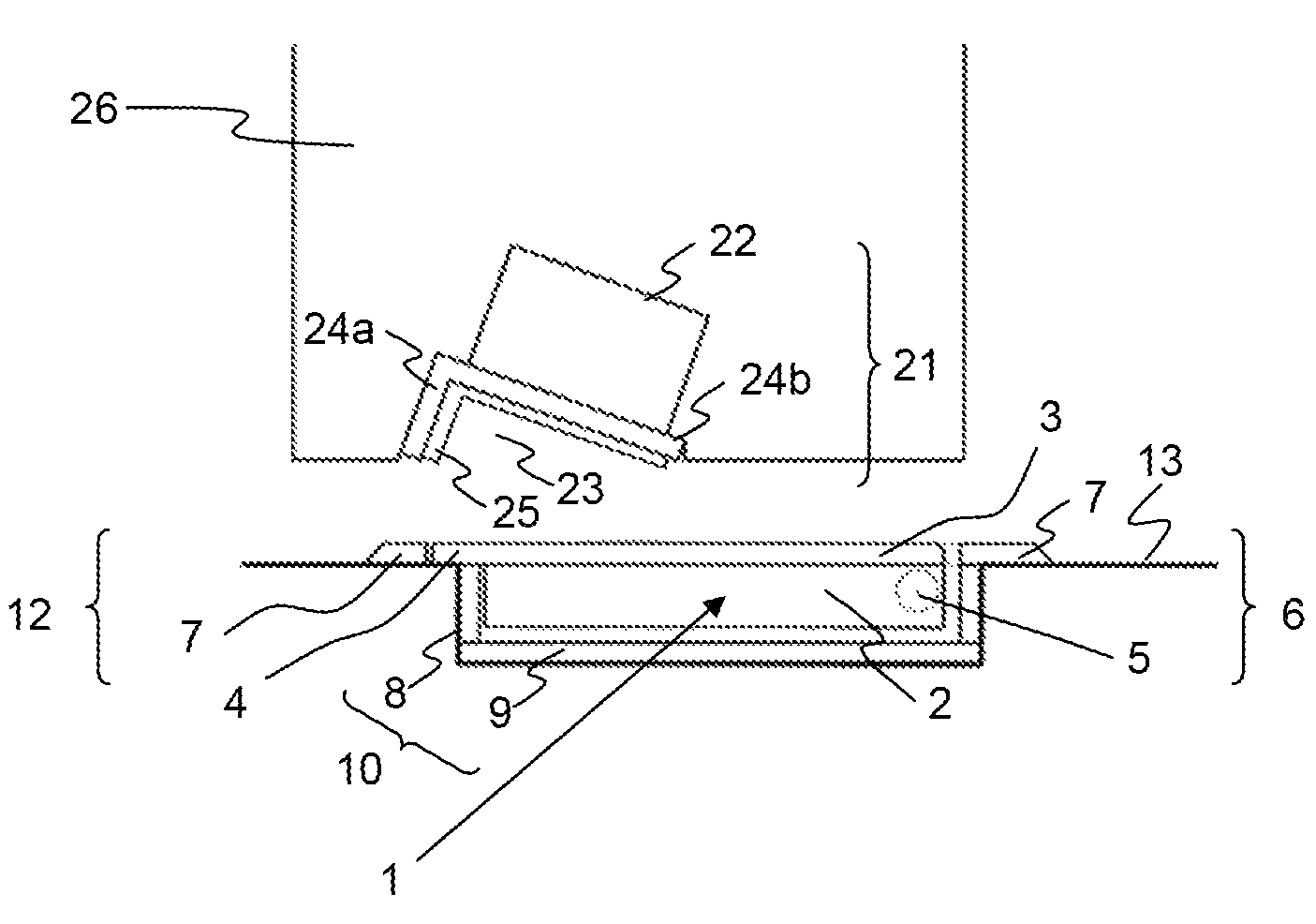
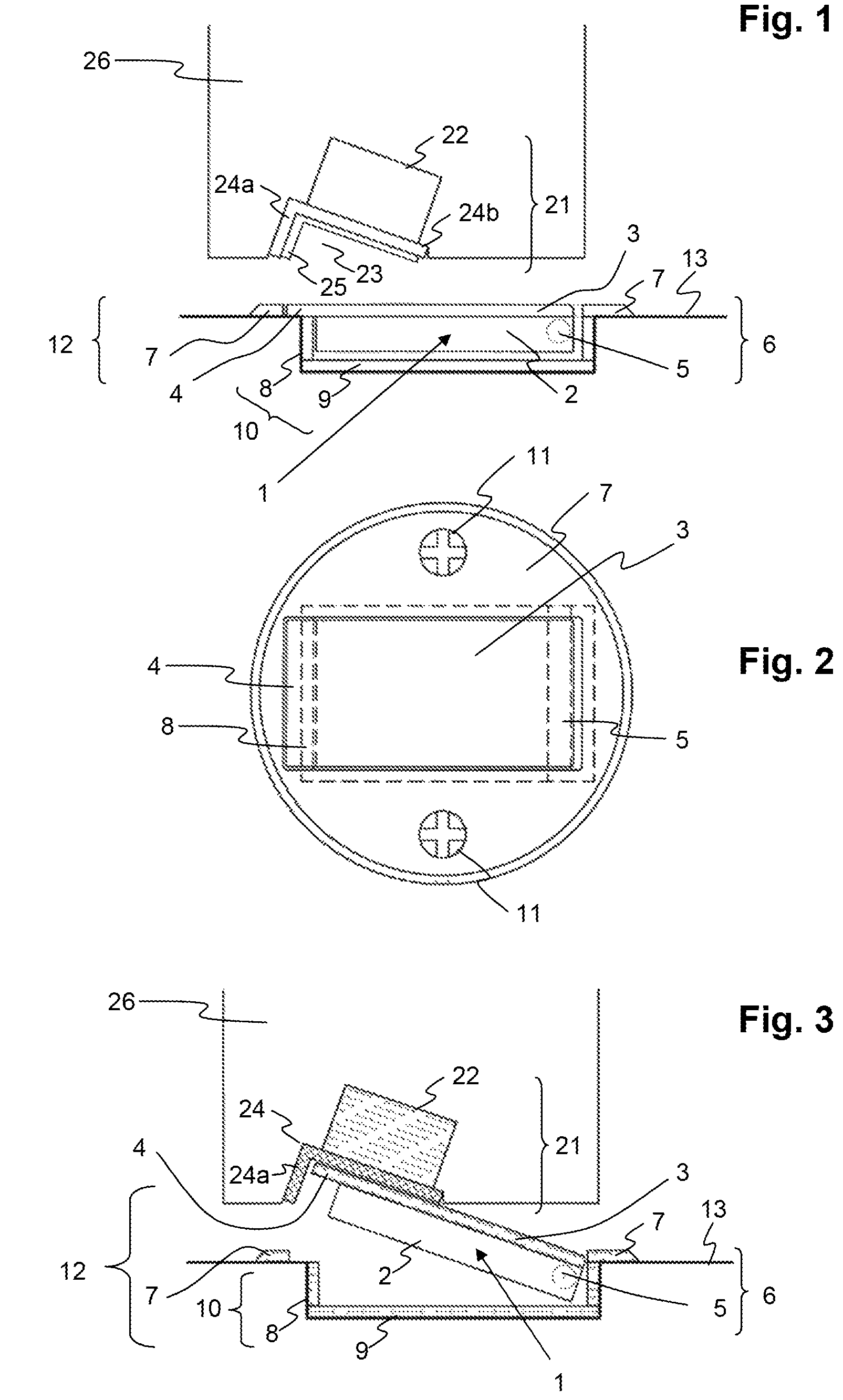
[0039]FIGS. 1 to 3 show one preferred embodiment of the invention, in which the same numbers in each case denote the same parts: a tilting element 1 is installed in the floor and equipped with a cover plate 3 composed of chromium steel and with a counter-sunk housing 6 with a bezel 7, likewise composed of a chromium steel plate of the same thickness. The tilting element 1 and the housing 6 together form a securing element 12. However, a tilting element 1 used without a housing 6 can also be referred to as a securing element 12.

[0040]A counter element 21 is installed in the bottom end face or bottom edge of a door 26. A notch 23 in the counter element 21 is provided to accommodate the raised tilting element 1. The notch 23 is covered by an angle profile 24, for example composed of metal or plastic. In addition, the surface of the angled profile 24 is equipped with a buffer zone 25 of elastic material, such as rubber. FIG. 3 shows an exemplary embodiment without a buffer zone 25.

[0041...


PUM


Abstract

A device for securing or stopping a door relative to a stationary structure by means of magnetic attraction. In a secured position, a tilt element engages a counter-element due to magnetic attraction between the first magnetic element and the second magnetic element, and the door is stopped and optionally fixed in place, while in a retracted position the tilt element is retracted and the door can be moved. The tilt element includes a cover plate made of non-magnetic solid material and can be installed both on the stationary structure, such as the floor, wall or ceiling, or in the door.

Description

BACKGROUND OF THE INVENTION[0001]1. Field of the Invention[0002]The subject matter of the present invention is a device according to the generic term of the first independent patent claim and which is used to secure doors by means of magnetic attraction.[0003]2. Description of Related Art[0004]Magnetic door stoppers are known from prior art, having magnetic parts installed in the door and in the floor and resulting in a door being stopped as it moves across the magnetic part positioned in the floor.[0005]By way of example, inter alia, CH 383,822 discloses a stop device in which a permanent magnet, which is installed in the door, raises a moving ferromagnet, which is incorporated in the floor, and draws it into a slot in the door which is constructed for this purpose. This stops further movement of the door in the same direction. However, the magnetic attraction force of a conventional permanent magnet is too weak to also secure the door.[0006]U.S. Pat. No. 6,321,411 deals with this ...

Claims


Application Information

Patent Timeline
Patent Type & Authority Patents(United States)
IPC IPC(8): E05C17/56E05C19/16
CPCE05C17/56Y10T292/11
Inventor BOSSHARD, VIKTOR
Owner JOS BERCHTOLD
Why Eureka
Try Eureka