Manipulator

a manipulator and hand-held technology, applied in the field of manipulators, can solve the problems of more tedious and time-consuming cleaning of manipulators, limited cases that can be handled under the usual training practice of endoscopic surgery, etc., and achieve the effect of cleaning with eas

Active Publication Date: 2013-02-26
KARL STORZ GMBH & CO KG
View PDF19 Cites 816 Cited by
  • Summary
  • Abstract
  • Description
  • Claims
  • Application Information

AI Technical Summary

Benefits of technology

[0011]It is an object of the present invention to provide a manipulator which prevents blood or the like from flowing into the shaft to a maximum extent and which can be cleaned with ease.
[0012]According to an aspect of the present invention, there is provided a manipulator comprising a hollow shaft, a power transmitting member extending through the hollow shaft, a drive mechanism mounted on one end of the hollow shaft, for imparting a drive force to the power transmitting member, a distal-end working unit mounted on another end of the hollow shaft, for being actuated by the power transmitting member, and a sealing member for preventing liquid from flowing from the distal-end working unit through the hollow shaft to the drive mechanism, the sealing member having a hole defined therein, the power transmitting member being slidably inserted through the hole.
[0013]The sealing member is capable of blocking the liquid tending to flow from the distal-end working unit through the hollow shaft to the drive mechanism. Therefore, the liquid is prevented from being introduced deeply into the hollow shaft and the drive mechanism. The manipulator can thus be cleaned easily after use, and hence can easily be serviced for maintenance. Also, since the sealing member is capable of blocking air flow in the shaft, air is substantially sealed in the interior of the shaft on the distal end working unit side of the sealing member. Thus, the sealed air can prevent blood or the like from flowing into the shaft, to a maximum extent.

Problems solved by technology

Therefore, cases that can be handled under the usual training practice for endoscopic surgery are limited to a certain range, and the surgeon need to be trained and skilled to a considerably high level in order to be able to perform endoscopic surgery on various other cases not in the limited range.
If the blood and body fluids have entered the slender shaft and the main body, then it is more tedious and time-consuming to clean the manipulator.

Method used


Image

  • Manipulator
  • Manipulator
  • Manipulator

Examples


Embodiment Construction

[0042]Manipulators according to embodiments of the present invention will be described below with reference to the accompanying drawings.

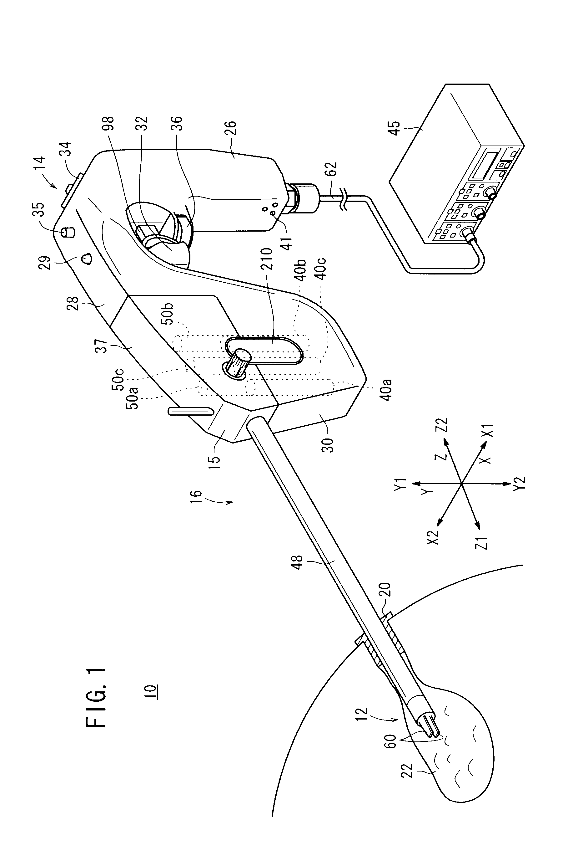
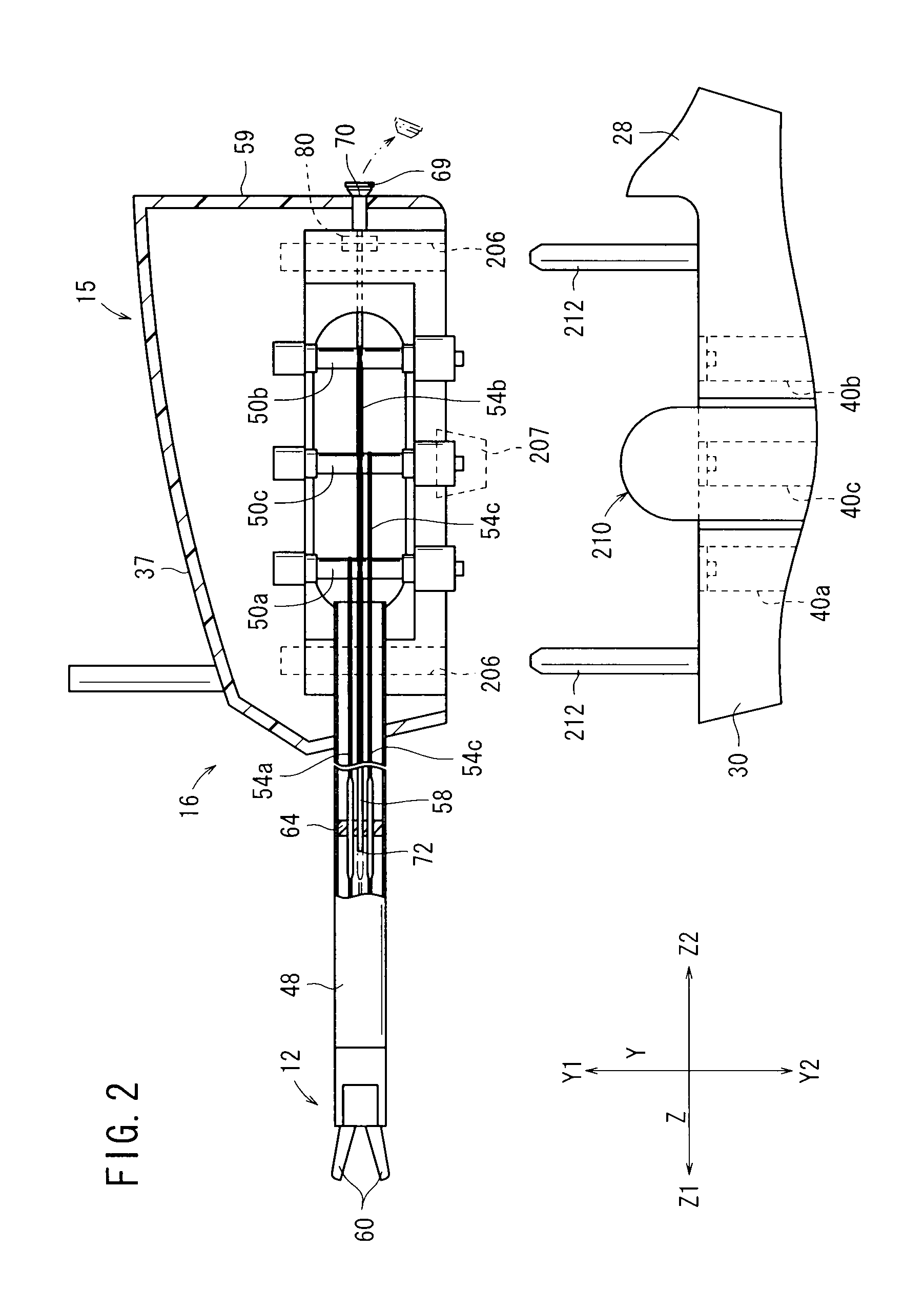
[0043]As shown in FIG. 1, a manipulator 10 according to an embodiment of the present invention is a medical manipulator having a distal-end working unit 12 for gripping a portion of a living tissue, a curved needle, or the like for performing a certain surgical treatment, and is usually referred to as gripping forceps or a needle driver (needle holder).

[0044]The manipulator 10 comprises an operation command unit 14 which is held and operated by hand and a working unit 16 detachably mounted on the operation command unit 14.

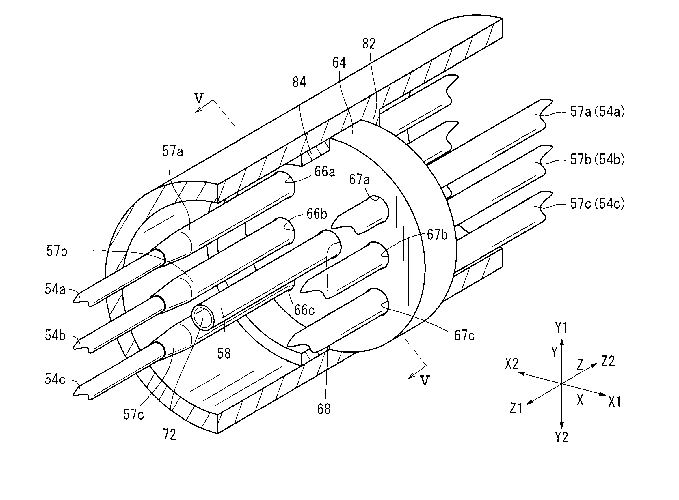
[0045]It is assumed in the following description that transverse directions in FIG. 1 are referred to as X directions, vertical directions as Y directions, and longitudinal directions of a joint shaft 48 as Z directions. Of the X directions, the rightward direction as viewed from the distal end is referred to as an X1 direction, a...


PUM


Abstract

A manipulator includes a hollow joint shaft, wires extending through the joint shaft, pulleys mounted on an end of the joint shaft, for imparting a drive force to the wires, a distal-end working unit mounted on another end of the joint shaft, for being actuated by the wires, and a sealing member for preventing liquid such as blood from flowing from the distal-end working unit through the joint shaft to a connector. The sealing member has holes defined therein, and the wires are slidably inserted through the holes.

Description

BACKGROUND OF THE INVENTION[0001]1. Field of the Invention[0002]The present invention relates to a manipulator for operating a distal-end working unit through power transmitting members.[0003]2. Description of the Related Art[0004]According to endoscopic surgery (also called laparoscopic surgery), it is customary to form a plurality of holes or incisions in the body surface (abdomen or the like) of the patient, insert trocars (tubular instruments) into the respective incisions as instrument passage ports, and introduce tip ends of forceps having shafts through the respective trocars into the body cavity to perform the surgical operation on the affected part of the body. Working units such as a gripper for gripping a living tissue, scissors, the blade of an electrosurgical knife, etc. are mounted on the tip ends of the forceps.[0005]The endoscopic surgical operation performed with forceps requires the surgeon to be trained in advance because the working space in the body cavity is sm...

Claims


Application Information

Patent Timeline
Patent Type & Authority Patents(United States)
IPC IPC(8): A61B17/00
CPCA61B17/29A61B19/22A61B2017/2901A61B2017/2925A61B2017/2929A61B2017/2932A61B2017/2948A61B2019/2249A61B2019/4868A61B2217/007A61B34/70A61B34/72A61B2090/0813
Inventor UENOHARA, SHUICHISANO, HIROAKI
Owner KARL STORZ GMBH & CO KG
Why Eureka
Try Eureka