PWM signal generator, and inverter equipped with this PWM signal generator

a technology of pwm signal generator and pwm signal, which is applied in the direction of pulse technique, process and machine control, instruments, etc., can solve the problems of difficult unit construction, inability to take advantage of good universality and flexibility in the design of the digital control system,

Active Publication Date: 2013-02-26
NAT UNIV CORP NAGAOKA UNIV TECH +2
View PDF15 Cites 12 Cited by
  • Summary
  • Abstract
  • Description
  • Claims
  • Application Information

AI Technical Summary

Benefits of technology

[0015]The present invention has been proposed under the above situation, and it is an object of the present invention to provide a PWM signal generator that solves the drawbacks to current control by hysteresis and which generates PWM signals with a longer period by means of a digitized control system, and an inverter device that is equipped with this PWM signal generator.

Problems solved by technology

(1) A circuit is necessary to constantly monitor whether the AC current actually outputted from the system-linked inverter device departs from the allowable range or not.
(2) It is difficult to construct a unit in which a pattern of PWM signals is generated according to whether the AC current actually outputted from the system-linked inverter device departs from the allowable range, using a digital control system. Accordingly, good universality and flexibility cannot be taken advantage of in the design of the digital control system.

Method used


Image

  • PWM signal generator, and inverter equipped with this PWM signal generator
  • PWM signal generator, and inverter equipped with this PWM signal generator
  • PWM signal generator, and inverter equipped with this PWM signal generator

Examples


first embodiment

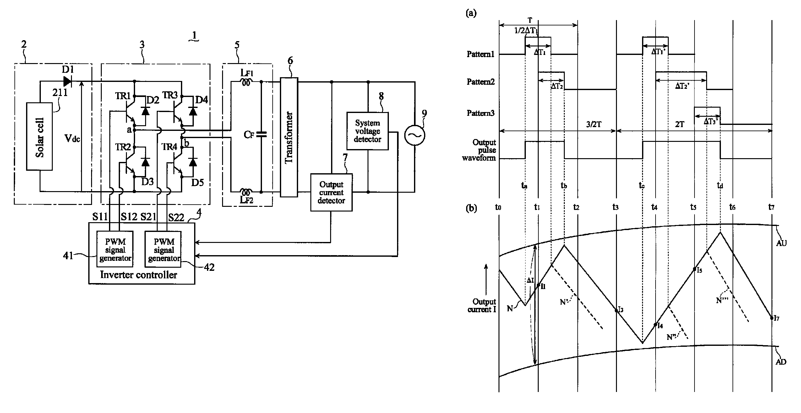
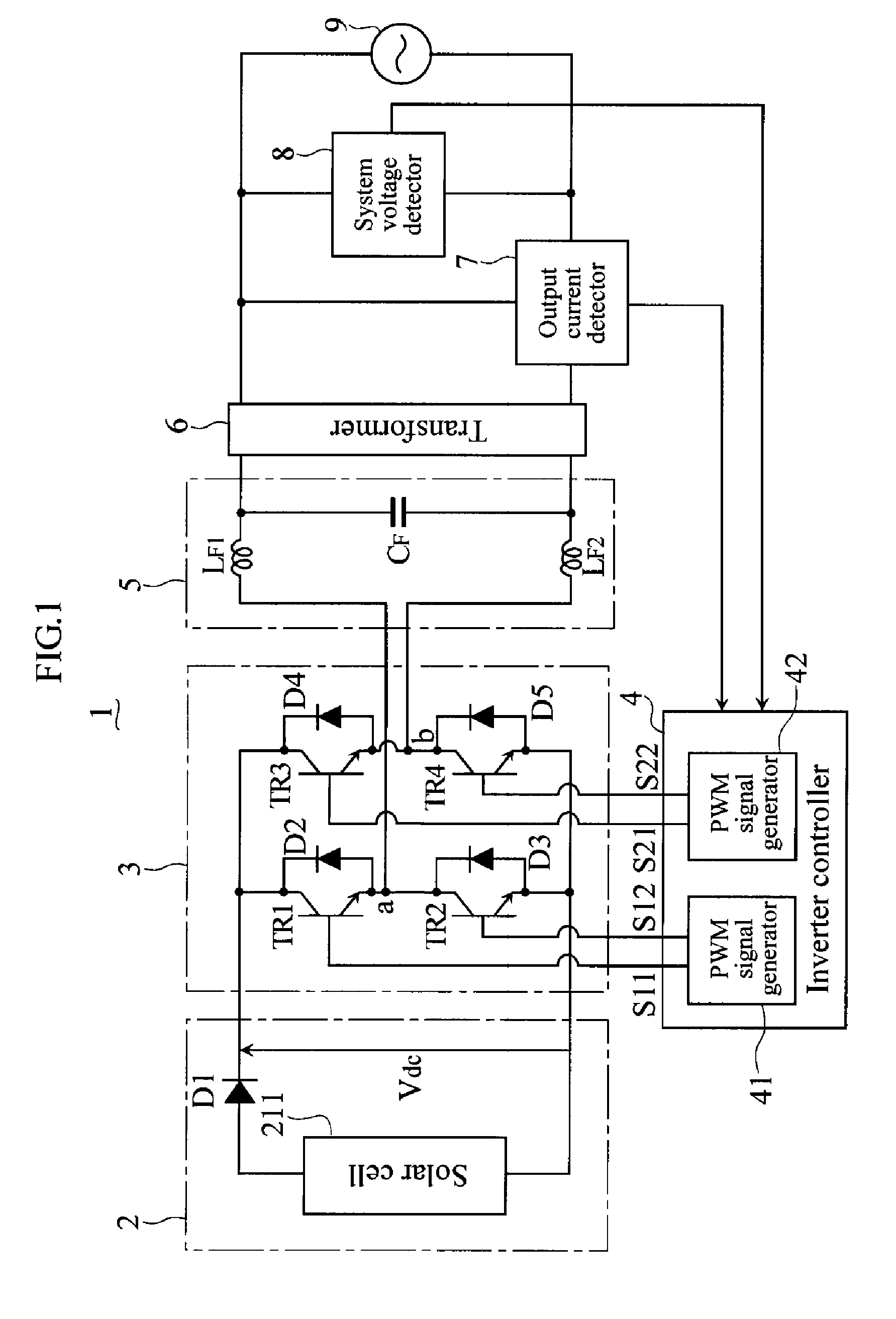
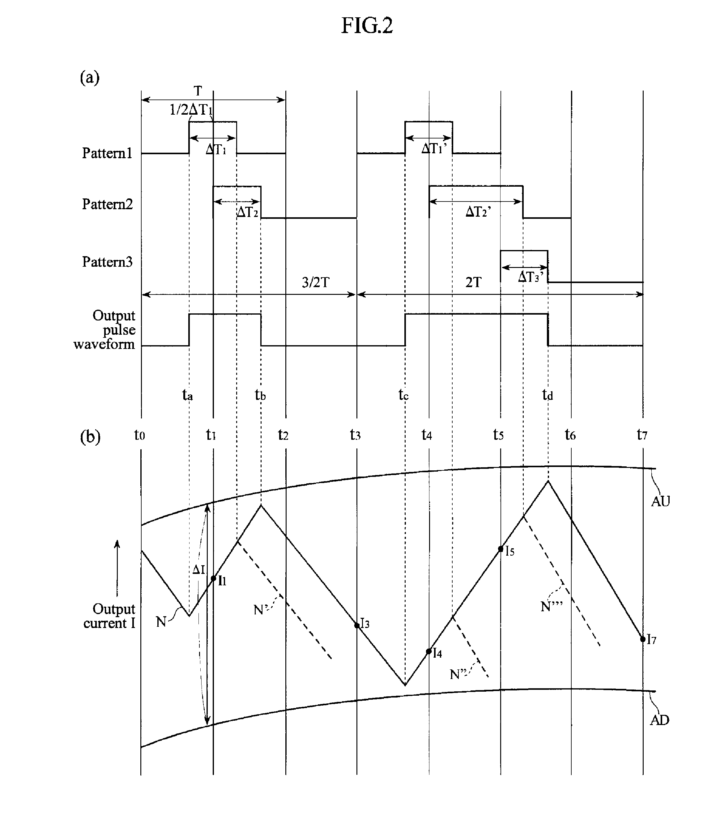
[0077]The method for generating the PWM signals generated by the inverter controller 4 will now be described in detail with reference to FIGS. 2 and 3. The following is a description of a first embodiment in which the previously determined pulse waveform is A type, the pulse waveform determined by recalculation is B type, the periods of the pulse waveforms are the same, the position of the on-duration of the previously determined pulse waveform is disposed in the middle of the period, and the timing of the recalculation is in the middle of the period of the previously determined pulse waveform.

[0078]FIG. 2 is a diagram illustrating the method for generating the PWM signal that is generated by the inverter controller 4. FIG. 2(a) is a waveform diagram showing how two kinds of pulse waveform are combined into an output pulse waveform. FIG. 2(b) is a diagram showing the relation between the output pulse waveform and the output current I of the inverter circuit 3, and corresponds to FIG...

second embodiment

[0175]FIG. 9 is a diagram illustrating a case of the first pulse waveform in which the on-duration is shifted from the middle of one period (hereinafter this case will be referred to as the “second embodiment”).

[0176]As shown in FIG. 9(a), the first pulse waveform is generated as a pulse waveform in which the middle of the on-duration of the first on-time ΔT1 is located at (⅓)·T. This first pulse waveform comes on after the elapse of the time {(⅓)·T−(½)·ΔT1} since the time instant at which the first on-time ΔT1 was computed (the time instant at the start of one period T), and goes off after the elapse of the time {(⅓)·T−(½)·ΔT1}. Here again, the second on-time ΔT2 is computed for when T is one period after the elapse of the time (½)·T.

[0177]FIG. 9(b) shows a second pulse waveform having the on-duration of the second on-time ΔT2. This second pulse waveform comes on at the time instant at which the second on-time ΔT2 was calculated (the time instant of (½)·T in one period T), and goes...

third embodiment

[0184]FIG. 10 is a diagram illustrating when the calculation of the second on-time ΔT2 is performed at a predetermined timing since the calculation of the first on-time ΔT1 (hereinafter referred to as the “third embodiment”).

[0185]FIG. 10(a) shows a first pulse waveform having an on-duration of the first on-time ΔT1 in which the pulse waveform is such that the on-duration is located in the middle of one period. This first pulse waveform comes on after the elapse of the time (½)·(T−ΔT1) since the time instant at which the first on-time ΔT1 was computed (the time instant at the start of the period T of the first pulse waveform), and goes off after the elapse of the time (½)·(T+ΔT1).

[0186]In this example, the second on-time ΔT2 is computed for when T is used as one period after the elapse of the time (⅓)·T since the time instant at the start of the period T of the first pulse waveform. FIG. 10(b) shows a second pulse waveform having an on-duration of the second on-time ΔT2. This second...


PUM


Abstract

The PWM signal generator of the present invention generates a first pulse waveform in which a first on-time ΔT1 calculated by a first on-time calculator (401) is used as an on-duration, and a second pulse waveform in which a second on-time ΔT2, calculated by a second on-time calculator (402) when a preset delay time has elapsed from the start of the calculation of the first on-time ΔT1, is used as an on-duration. Also, a PWM signal generator (413) generates a PWM signal on the basis of a composite pulse in which the generated first pulse waveform and second pulse waveform are combined, and the first on-time calculator (401) calculates the first on-time ΔT1 at the end of the composite pulse waveform.

Description

TECHNICAL FIELD[0001]This invention relates to a PWM signal generator that generates pulse waveforms and to an inverter device equipped with this PWM signal generator.BACKGROUND ART[0002]Conventionally, system-linked inverter devices have been developed with which power was supplied by linking DC power generated by a fuel cell, solar cell, or the like to a commercial power system. With this system-linked inverter device, a technique is proposed for reducing switching loss by reducing the number of times switching elements have to switch.[0003]For example, Japanese Patent Application Laid-open No. H11-53042 discloses a technique for reducing switching loss by reducing the number of times switching elements have to switch in the region of practical use. Such reduction is achieved by setting the frequency of a triangular wave for generating a PWM (pulse width modulation) signal that controls the on / off operation of the switching elements to 20 kHz when the inverter output power Pout is...

Claims


Application Information

Patent Timeline
Patent Type & Authority Patents(United States)
IPC IPC(8): H02M3/335H02M1/12
CPCH02M7/53871H02M2001/0048Y02B70/1491Y02B70/10H02M1/0048
Inventor HATTORI, NOBUYUKIOHTA, YOSHITOHIRATA, KENJI
Owner NAT UNIV CORP NAGAOKA UNIV TECH
Why Eureka
Try Eureka