Sparse data environmental equipment threshold compliance alarm system and method

a technology of environmental equipment and alarm system, applied in the field of environmental equipment, can solve the problems of environmental problems, untreated wastewater from the system, and cannot realistically afford to employ personnel, and achieve the effect of inexpensive monitoring

Active Publication Date: 2013-02-26
JERRY L MCKINNEY 2002 TRUST
View PDF25 Cites 19 Cited by
  • Summary
  • Abstract
  • Description
  • Claims
  • Application Information

AI Technical Summary

Benefits of technology

[0018]Accordingly, it is an objective of the present invention to provide an improved service personnel detection system and method capable of inexpensively monitoring large numbers, perhaps tens or hundreds of thousands, of remotely located and / or widespread environmental equipment systems to determine operational compliance.
[0019]An objective of one preferred embodiment of the present invention is to provide an improved system and method that permits responsible parties and / or government agencies to automatically monitor compliance by service providers in providing maintenance and repairs to their environmental equipment systems.

Problems solved by technology

Many low volume wastewater treatment plants are owned by individual homeowners or small entities who cannot realistically afford to employ personnel on a daily basis to maintain and repair their wastewater treatment facility.
If the systems do not operate properly, then untreated wastewater from the system may eventually reach local streams.
If such problems occur frequently with thousands of small systems, then environmental problems could result.
However, in some cases, wastewater input to the system on a short term basis may far exceed the daily permit allowance.
For instance, a system rated for treating 500 gallons per day may be abused on a short term basis, e.g., local gatherings and the like, and may have, for example only, 2000 gallons run through the system for one or more days.
This may have negative environmental and / or economic impact such as untreated wastewater passing through the system, drainage back-ups, overflows, damage to buildings, and the like.
However, the communication systems have the effect of significantly increasing operating costs due to the requirement for a dedicated communication line.
Other types of environmental systems have different problems.
However, filters are problematic in that they become plugged and need to be cleaned or replaced.
This requires manpower and simple schedules for cleaning the filters tend to be inefficient.
This type of information is costly to obtain due to the large number and wide constructions subject to such requirements.
The netting system does not provide an alarm and instead requires schedule maintenance that may comprise many inefficiencies as noted above.
For those types of environmental systems that do utilize alarms, the alarm circuit for the systems, like any other component, may also malfunction or lose power.
If the alarm circuit is not operational, then problems may remain undetected.
Otherwise, the power to the alarm circuit may fail without observation by the homeowner.
Additional telephone lines may incur additional costs if necessary for sending / receiving data.
Homeowners are often required by regulations to renew their initial service contract, which may be for two years, for as long as the equipment is utilized; however, after extensive review and research in this industry, the inventor has identified significant problems that still exist with such systems and that are discussed hereinafter in some detail.
For instance, when homeowners obtain a service contract, it is often difficult for homeowners to verify that the required maintenance has actually been performed and that repairs have been made by the service companies in a timely manner.

Method used


Image

  • Sparse data environmental equipment threshold compliance alarm system and method
  • Sparse data environmental equipment threshold compliance alarm system and method
  • Sparse data environmental equipment threshold compliance alarm system and method

Examples


Embodiment Construction

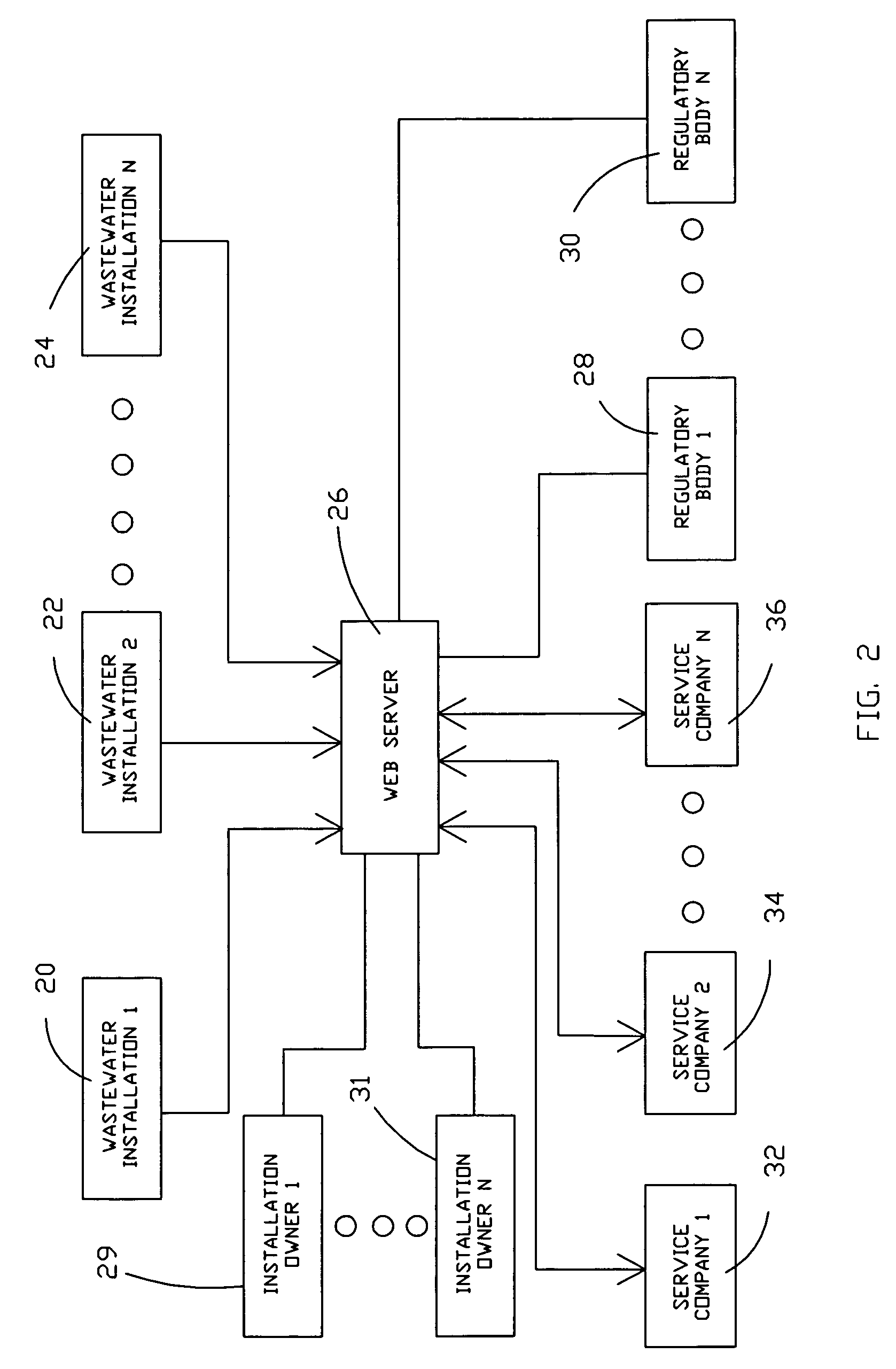
[0070]With small environmental systems, the systems may be serviced by different service companies, owned by different owners, and located at different locations. Generally, as used herein, different locations will also refer to different portions of land typically owned by different owners. The locations may be adjacent each other or separated by thousands of miles; however, the invention could also be utilized to monitor multiple environmental equipment systems on premises owned by a single owner such as a large plant, refinery, or the like with many different systems spread out over a wide area. The invention could also be utilized by a plurality of such plants or refineries located in different geographical areas of a country or in different countries to thereby permit improved compliance control by appropriate regulatory bodies.

[0071]Monitoring systems for environmental equipment such as environmental systems are known, as discussed hereinbefore; however, the inventor has deter...


PUM

PropertyMeasurementUnit
timeaaaaaaaaaa
timeaaaaaaaaaa
depthaaaaaaaaaa

Abstract

A sparse data system is provided for verifying operational compliance of a plurality of environmental systems. To reduce operational costs to a minimum, the quantity of data transmitted is minimized and the data is only transmitted at certain times. If systems are compliant, then information is preferably not sent. If systems are non-compliant, then notices are sent to parties of interest at effectively the same time as the noncompliance occurs. Subsequent alarm detection level may also be sent after detection of an operational threshold to provide notice for continued ongoing or severe noncompliance.

Description

CROSS REFERENCE TO RELATED APPLICATIONS[0001]This application is a continuation-in-part application of U.S. patent application Ser. No. 10 / 003,633 filed on Nov. 2, 2001 now U.S. Pat. No. 7,149,701 and a continuation-in-part of U.S. patent application Ser. No. 11 / 586,864 entitled SPARSE DATA ENVIRONMENTAL EQUIPMENT THRESHOLD ALARM SYSTEM AND METHOD and filed Oct. 26, 2006.BACKGROUND OF THE INVENTION[0002]1. Field of the Invention[0003]The present invention relates generally to environmental equipment and, more particularly to a very low cost permit threshold detection system method that may be utilized for monitoring a large number of typically wide spread environmental equipment systems, which may be of various types, to verify environmental permit compliance on a near real time basis.[0004]2. Description of the Prior Art[0005]Many low volume wastewater treatment plants are owned by individual homeowners or small entities who cannot realistically afford to employ personnel on a dail...

Claims


Application Information

Patent Timeline
Patent Type & Authority Patents(United States)
IPC IPC(8): G06Q10/00G06Q99/00C02F1/00G05B15/02G05B23/02G06Q50/00H04Q9/00
CPCG06Q10/06G06Q10/06395G06Q10/20G06Q30/018C02F2209/008C02F2303/14G06Q50/00H04Q9/00H04Q2209/823Y02W10/37
Inventor MCKINNEY, JERRY L.
Owner JERRY L MCKINNEY 2002 TRUST
Why Eureka
Try Eureka