Drive train arrangement for a vehicle

a technology for driving trains and vehicles, which is applied to vehicle components, control devices, vehicle transmissions, etc., can solve the problems of increasing the structural fitting space required for the transmission of the vehicle, and the vehicle cannot be all-wheel operated, so as to achieve efficient space saving, inexpensive and weight-reducing effects

Inactive Publication Date: 2013-03-05
ZF FRIEDRICHSHAFEN AG
View PDF21 Cites 4 Cited by
  • Summary
  • Abstract
  • Description
  • Claims
  • Application Information

AI Technical Summary

Benefits of technology

[0008]Thus, even a displacement of the front axle differential transmission, made necessary by the design of the vehicle, can be compensated for by virtue of the drive train arrangement according to the invention, without for example having to use a further connecting shaft with the corresponding articulations. In this way, depending on the type of the vehicle concerned the arrangement position of the front axle transmission can be changed without having to change the fixing position on the vehicle. By using the adaptor device or a like component with the drive train arrangement proposed according to the invention, the connection of the front axle differential at the solid angle of the connecting shaft predetermined by the design can be adapted in the most simple manner without the cost-intensive production of variants, for example the provision of different housing variants and the use of additional components.
[0009]Consequently, the drive train arrangement according to the invention enables the most efficient space-saving, inexpensive and weight-reduced possible connection of the front axle or front axle differential transmission to the drive train.

Problems solved by technology

In this known drive train the front axle transmission on the front axle of the vehicle is not driven, so no all-wheel operation is possible with this vehicle.
This increases the structural fitting space required for the vehicle transmission.

Method used


Image

  • Drive train arrangement for a vehicle
  • Drive train arrangement for a vehicle
  • Drive train arrangement for a vehicle

Examples


Embodiment Construction

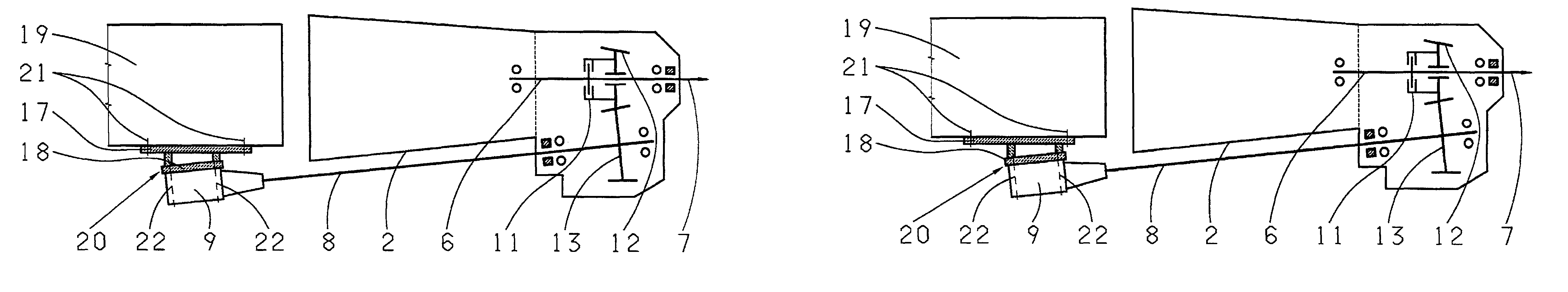
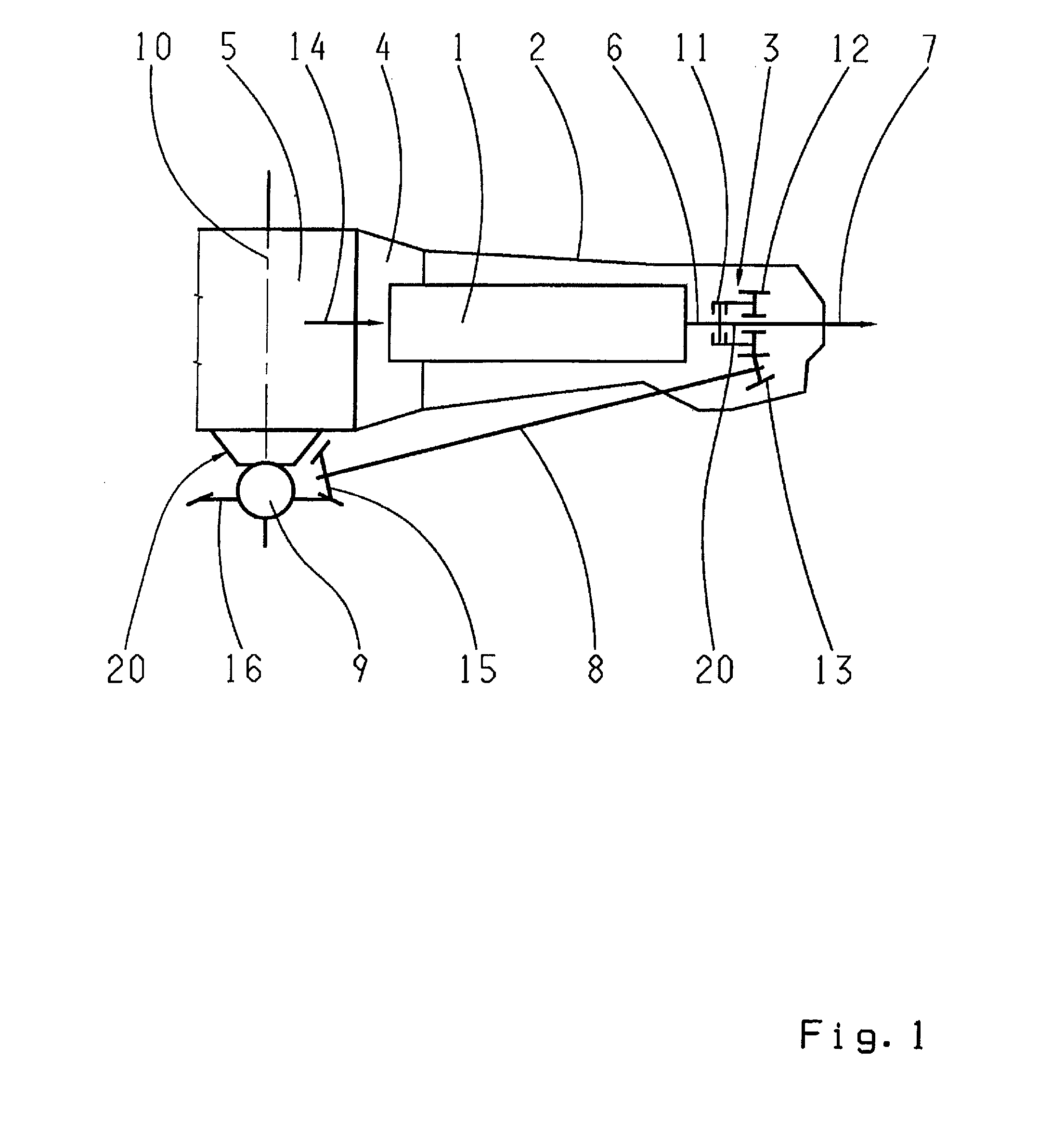
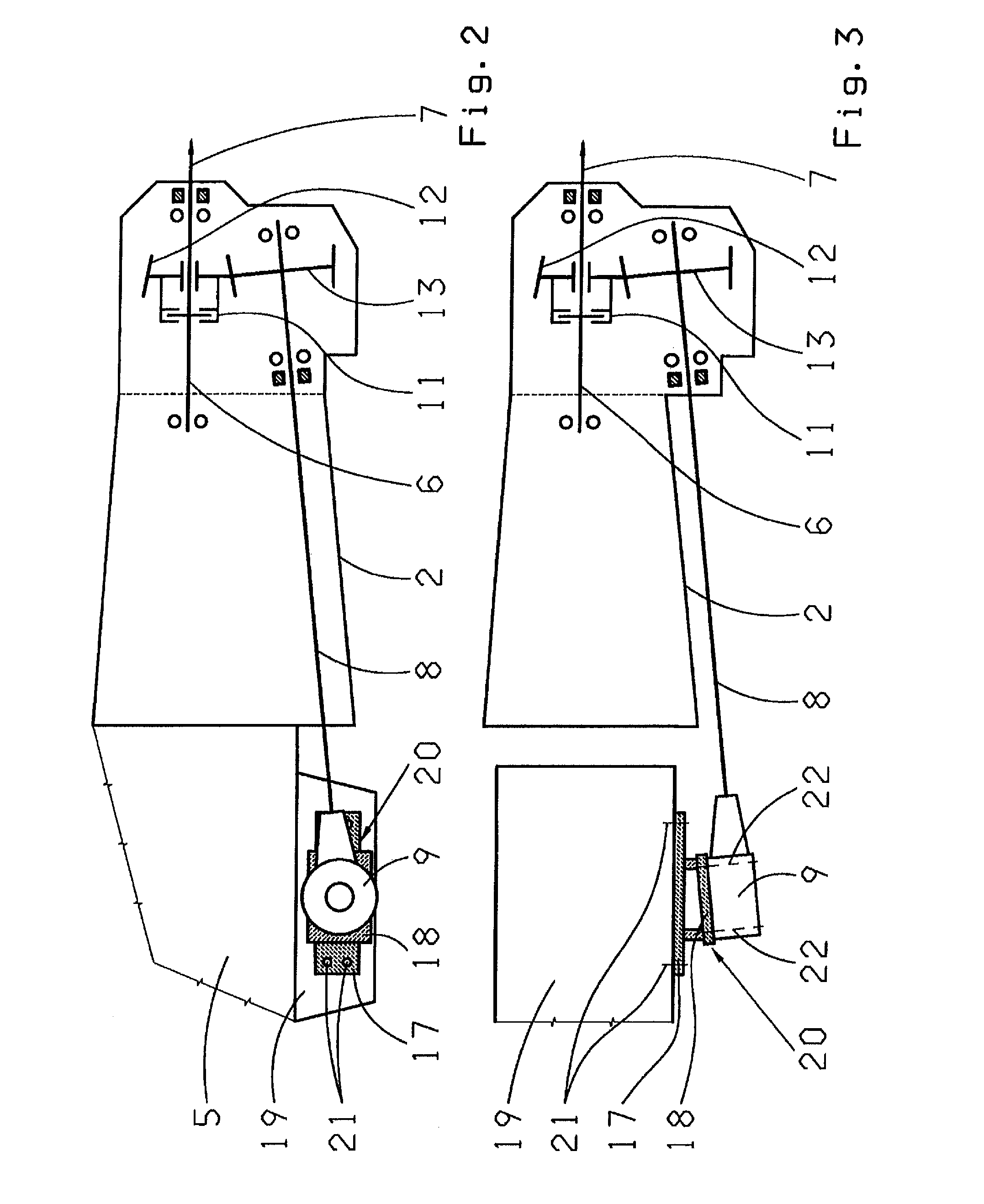
[0024]The figures illustrate a possible embodiment variant of a drive train arrangement according to the invention for a vehicle with a main transmission 1, in whose transmission housing 2 a transfer box 3 is integrated, chosen as an example. With the drive train arrangement according to the invention, for example a controllable all-wheel drive but also a purely rear-wheel drive or front-wheel drive can be provided.

[0025]FIG. 1 shows as an example a drive train arrangement for a controllable all-wheel drive system in a vehicle. The drive train comprises the main transmission 1, which is coupled to a drive engine 5 by a starting element 4 for torque transmission. The drive output shaft 6 of the main transmission 1 is connected to a shaft of the transfer box 3. The drive output of the transfer box 3 is connected permanently to a rear axle differential transmission indicated only schematically by an arrow 7. Furthermore, the drive output of the transfer box 3 can also optionally be cou...


PUM


Abstract

A drive train arrangement for a vehicle comprising a main transmission and a transfer box which are both housed within a transmission housing. The transfer box comprises a drive output which is connected to a rear axle differential transmission and connectable, by a torque transmission element and a connecting shaft, to a front axle differential transmission. The connecting shaft is arranged at a predetermined angle relative to the drive output shaft of the main transmission. The end of the connecting shaft, facing toward the front axle differential transmission, is actively connected to the front axle differential transmission. The front axle differential transmission is fixed to the vehicle by at least one adaptor device allowing the front axle differential transmission to be adapted to a variety of arrangement positions along the rotation axis of the connection shaft.

Description

[0001]This application is a National Stage completion of PCT / EP2009 / 060966 filed Aug. 26, 2009, which claims priority from German patent application serial no. 10 2008 042 044.1 filed Sep. 12, 2008.FIELD OF THE INVENTION[0002]The present invention concerns a drive train arrangement for a vehicle.BACKGROUND OF THE INVENTION[0003]From the document DE 30 36 445 C2 a transmission for vehicles with four-wheel drive is known. This known automatic transmission gearbox is connected downstream from a motor vehicle engine, such that the transmission gearbox is connected by its first output shaft to a driveshaft for the rear axle and by its second output shaft to a driveshaft for the front axle. The drive power for the front wheel drive is provided by a connection mechanism.[0004]Furthermore, from the document DE 20 2004 018 036 U1 another drive train for a motor vehicle is known. In this known drive train, the engine is positioned in front of the rear axle and behind the front axle. The drive...

Claims


Application Information

Patent Timeline
Patent Type & Authority Patents(United States)
IPC IPC(8): B60K17/16
CPCB60K17/35
Inventor MAIR, ULRICHROSEMEIER, THOMASGEHRING, DIETMARBAASCH, DETLEFBEIGANG, LOTHARGEIER, MANFRED
Owner ZF FRIEDRICHSHAFEN AG
Why Eureka
Try Eureka