Battery

a battery and structure technology, applied in the field of batteries, can solve the problems of overheating and heat generation of batteries, and achieve the effects of preventing short circuits, high capacity, and excellent safety

Active Publication Date: 2013-03-05
PANASONIC CORP
View PDF16 Cites 2 Cited by
  • Summary
  • Abstract
  • Description
  • Claims
  • Application Information

AI Technical Summary

Benefits of technology

[0031]According to the present invention, it is possible to prevent a short circuit between the battery case and the sealing plate or between the sealing plate and the terminal member even when the gasket is broken, and therefore to provide a battery having both an excellent safety and a high capacity.

Problems solved by technology

In the event when an internal short circuit or external short circuit occurs, and a short circuit current is caused to flow to generate Joule heat in a battery, the battery will generate heat and may become overheated.

Method used


Image

  • Battery
  • Battery
  • Battery

Examples


first embodiment

(i) First Embodiment

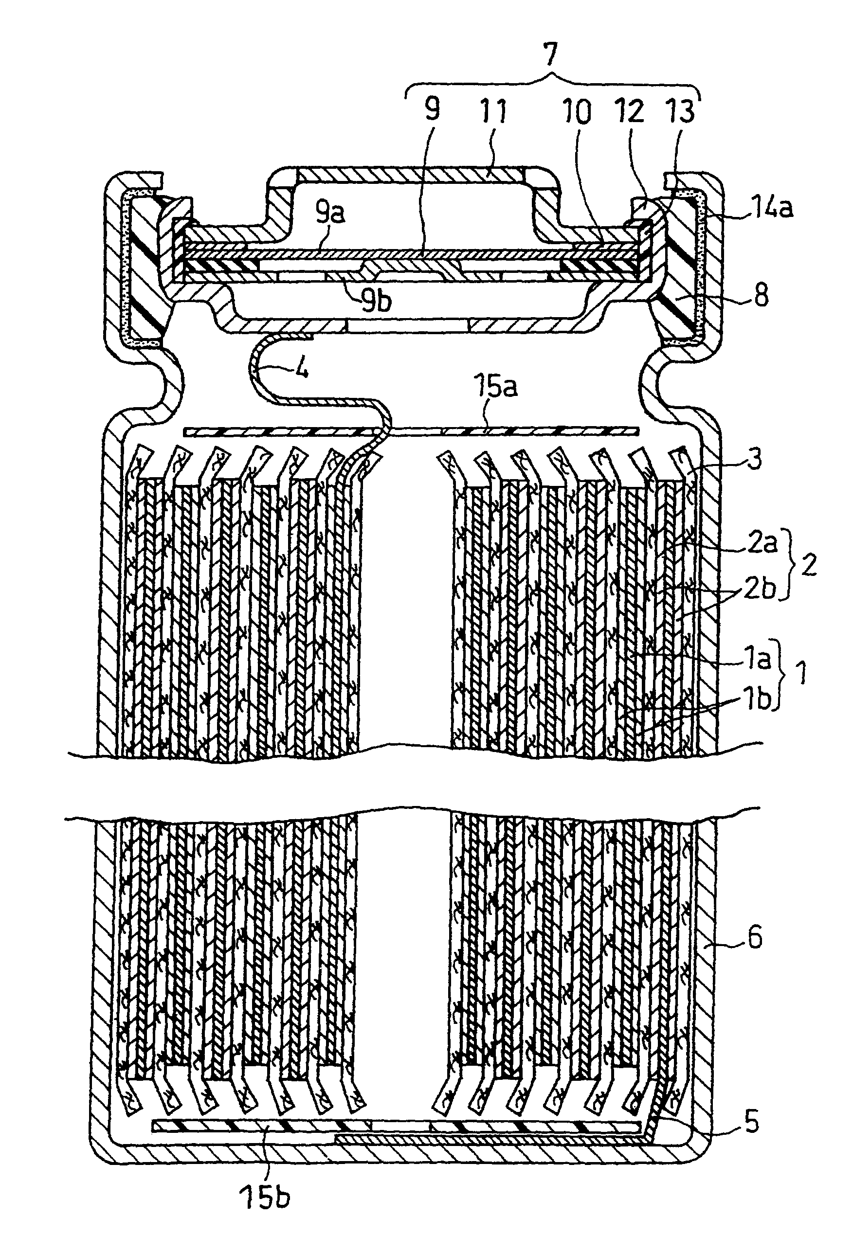
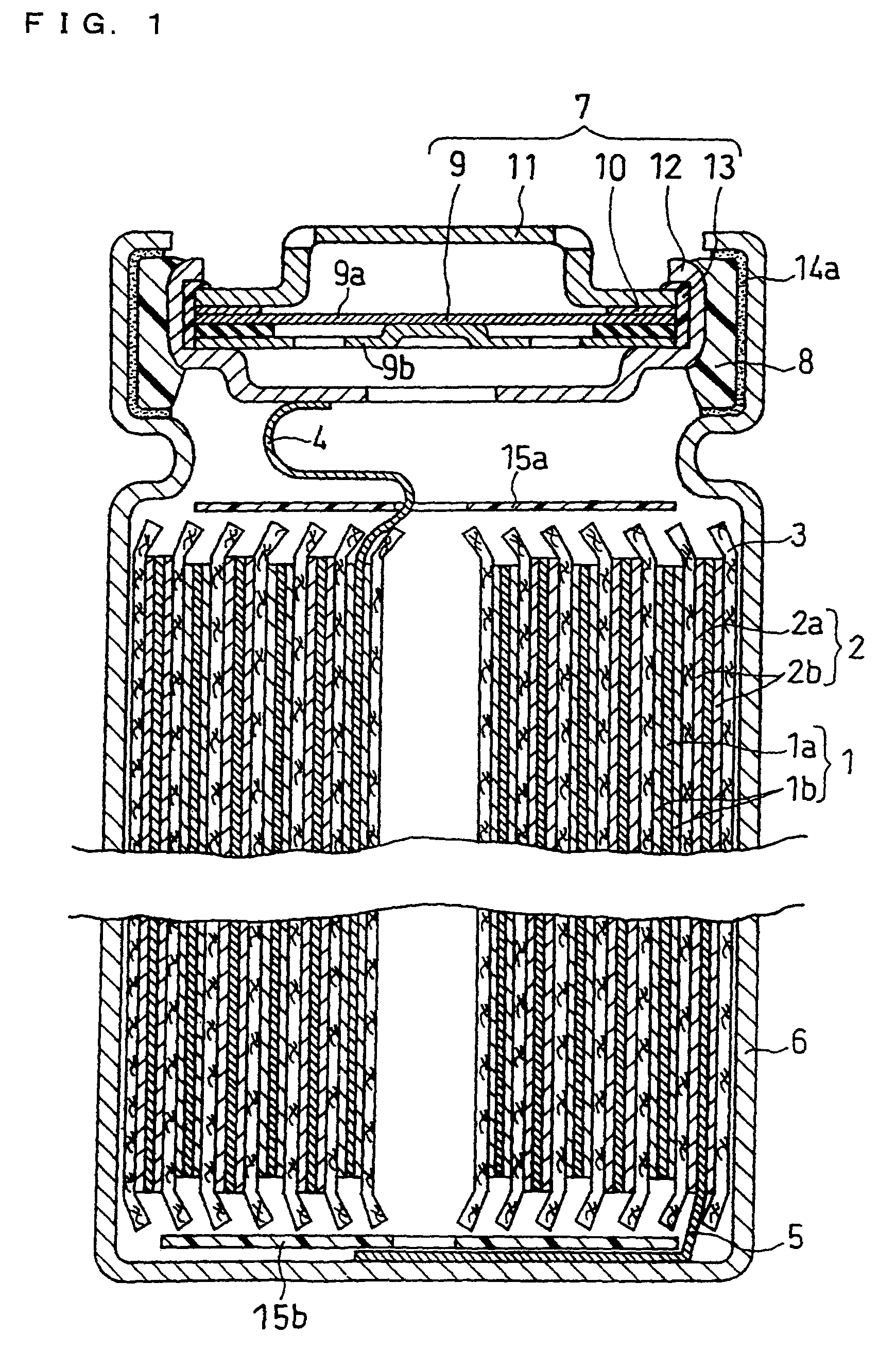
[0042]A battery according to this embodiment includes: a battery case having a bottom, a side wall, and an upper opening; an electrode assembly; an electrolyte; a sealing plate covering the upper opening of the battery case accommodating the electrode assembly and the electrolyte. The electrode assembly includes a positive electrode, a negative electrode, and a separator interposed between the positive electrode and the negative electrode. A gasket is interposed between the opening-edge portion of the battery case and the sealing plate. The battery of this embodiment has a first highly-resistive layer disposed between the opening-edge portion of the battery case and the gasket. By configuring as described above, it is possible to prevent a short circuit between the battery case and the sealing plate by virtue of the first highly-resistive layer when the gasket becomes thinner due to the inclusion of foreign matters and the like or even when the gasket is broken, ...

second embodiment

(ii) Second Embodiment

[0053]A battery according to this embodiment does not have the first highly-resistive layer disposed between the opening-edge portion of the battery case and the gasket and has a second highly-resistive layer disposed between the sealing plate and the gasket. By configuring as described above, it is possible to prevent a short circuit between the sealing plate and the battery case by virtue of the second highly-resistive layer even when the gasket is broken, and therefore to provide a battery having an excellent safety. The battery according to this embodiment basically has the same configuration as the battery according to the above-described first embodiment except the above, and the detailed description thereof is omitted. This embodiment is particularly suitable for cylindrical or coin batteries, but also applicable to prismatic batteries.

[0054]FIG. 3 is a longitudinal cross-sectional view schematically showing a cylindrical lithium ion secondary battery ac...

third embodiment

(iii) Third Embodiment

[0059]A battery according to this embodiment has both the first highly-resistive layer and the second highly-resistive layer. FIG. 5 is an enlarged view of a main part of a cylindrical lithium ion secondary battery according to this embodiment. The battery shown in FIG. 5 has the first highly-resistive layer 14a between the opening-edge portion of the battery case 6 and the gasket 8 and the second highly-resistive layer 14b between the sealing plate 7 and the gasket 8.

[0060]By providing both the first highly-resistive layer and the second highly-resistive layer, short circuit can be more reliably prevented, and a battery having a more excellent safety can be provided. Here, it is preferable that the first highly-resistive layer is disposed on an entire area where the battery case and the gasket face to each other, and the second highly-resistive layer is disposed on an entire area where the sealing plate and the gasket face to each other. This improves the effe...


PUM

PropertyMeasurementUnit
thicknessaaaaaaaaaa
thicknessaaaaaaaaaa
resistivityaaaaaaaaaa

Abstract

A battery including: a battery case having a bottom, a side wall, and an upper opening; an electrode assembly; an electrolyte; and a sealing plate covering the upper opening of the battery case accommodating the electrode assembly and the electrolyte, the electrode assembly including a positive electrode, a negative electrode, and a separator interposed between the positive electrode and the negative electrode, a gasket is interposed between an opening-edge portion of the battery case and the sealing plate, a first resistive layer is disposed between the opening-edge portion of the battery case and the gasket, or a second resistive layer is disposed between the sealing plate and the gasket. The first or second resistive layer contains a mixture of a particulate inorganic oxide and a binder. This configuration makes it possible to prevent a short circuit between the battery case and the sealing plate even when the gasket is broken.

Description

RELATED APPLICATIONS[0001]This application is the U.S. National Phase under 35 U.S.C. §371 of International Application No. PCT / JP2009 / 002424, filed on Jun. 1, 2009, which in turn claims the benefit of Japanese Application Nos. 2008-150946 and 2008-150947, both were filed on Jun. 9, 2008, the disclosures of which Applications are incorporated by reference herein.TECHNICAL FIELD[0002]The present invention relates to a structure of batteries, and particularly relates to an improvement of a structure of batteries for preventing short circuit.BACKGROUND ART[0003]Cylindrical, prismatic or coin batteries each include a battery case made of metal or the like, an electrode assembly and an electrolyte accommodated in the battery case, the battery case being sealed at its opening with a sealing plate. The positive electrode and the negative electrode are wound or stacked with a separator interposed therebetween, forming an electrode assembly. The separator provides electrical insulation betwe...

Claims


Application Information

Patent Timeline
Patent Type & Authority Patents(United States)
IPC IPC(8): H01M2/08H01M2/02H01M10/36H01M50/186H01M50/193
CPCH01M2/0413H01M2/1011H01M2/08H01M2/022H01M10/0525Y02E60/10H01M50/107H01M50/171H01M50/256H01M50/186H01M50/193
Inventor FUJIKAWA, MASATOYOKOYAMA, TOMOHIKO
Owner PANASONIC CORP
Why Eureka
Try Eureka