Eureka AIR delivers breakthrough ideas for toughest innovation challenges, trusted by R&D personnel around the world.

Flexible lens assembly with variable focal length

a flexible, lens technology, applied in the direction of instruments, printers, cameras, etc., can solve the problems of increasing the requirement for thin lens assemblies, difficult to assemble the lenses in a simple manner, and even greater challenges, so as to achieve compact adjustable lenses and improve optical focusing quality

Active Publication Date: 2013-03-05
POLIGHT +1
View PDF45 Cites 9 Cited by
  • Summary
  • Abstract
  • Description
  • Claims
  • Application Information

AI Technical Summary

Benefits of technology

This patent describes a lens assembly with two transparent covers that can be used to adjust the focus. The covers have piezo electric actuators that bend when electric voltage is applied, which allows the lens to change its shape. Surprisingly, even when only one of the covers has the actuators, the other cover can still bend and help change the focus. This allows for a wider range of focus adjustments and also protects the lens from damage. Additionally, the patent describes how the actuators on one of the covers can be controlled to work in conjunction with those on the other cover to fine-tune the focus. The transparent covers also have a prism that can change the direction of the light path in and out of the lens assembly.

Problems solved by technology

These challenges are even greater when the lens arrangement comprises tuneable parameters, such as encountered in auto focus lenses, wherein the focal length must be adjusted to fit the distance from the lens to the object to be photographed, for example.
Such lenses are usually complex designs comprising movable parts which can make it difficult to assemble the lens in a simple manner.
A further challenge with such designs is the ever increasing requirement to provide as thin lens assemblies as possible.
Filling and confining a liquid to a cavity may impose problems during both production and use, as known to a person skilled in the art.
However, the range of focal length adjustments is limited due to the limited range of bending of the floating glass cover.
If the actuating force is to high, the edge of the floating glass cover may cut the gel or elastomer located directly under the edge of the floating glass cover thereby damaging the lens body, and hence the range of focal length adjustments are limited by this possibility of damaging the lens body.

Method used


Image

  • Flexible lens assembly with variable focal length
  • Flexible lens assembly with variable focal length
  • Flexible lens assembly with variable focal length

Examples


Embodiment Construction

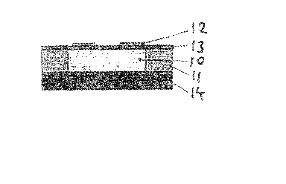
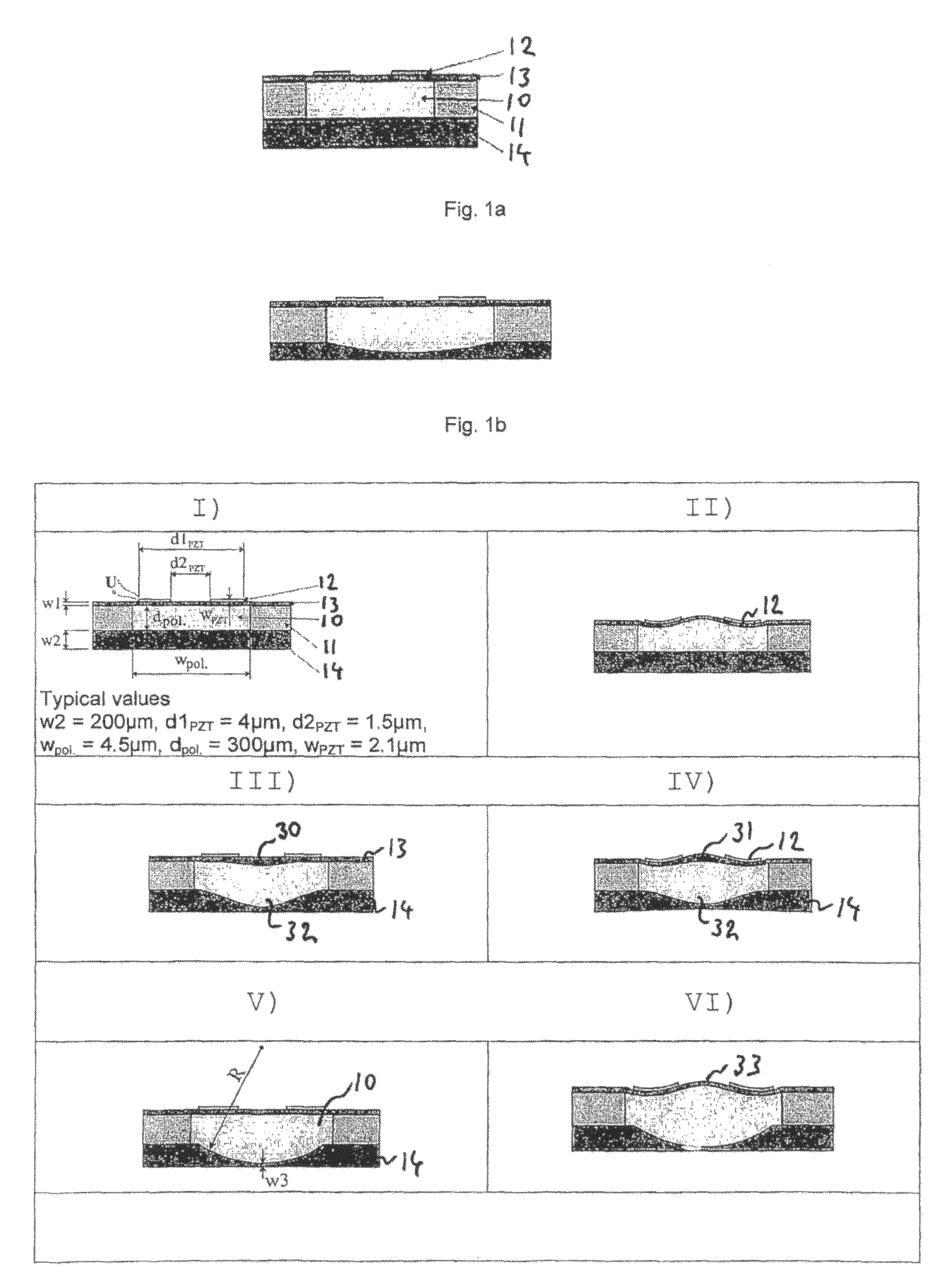
[0029]FIG. 1a illustrates an example of embodiment of the present invention comprising a lens body 10 made of a flexible material such as gel or elastomer materials bounded by sidewalls 11 and a first transparent cover13 and a second transparent cover 14. The example depicted in FIG. 1a comprises piezo electric elements 12 located on the first cover 13. The sidewall 11 is a continuous sidewall surrounding the whole lens body 10. When the piezo electric elements 12 are activated, an S shaped curvature is formed on the top of the first transparent cover in a region adjacent to the sidewall 11. An example of such an S shaped curvature is depicted in FIG. 2d.

[0030]According to an example of embodiment of the present invention, the piezo electric elements 12 are thin-film piezo actuators that are transparent.

[0031]According to another example of embodiment of the present invention, both transparent covers 13 and 14 may comprise piezo electric elements 12. When activated both transparent...


PUM


Abstract

The present invention is related to a lens assembly comprising a flexible lens body (10) inside a cavity bounded by a sidewall (11) and a first transparent cover (13), and a second transparent cover (14), wherein both covers (13,14) are in contact with respective surfaces of the lens body (10). Piezo electric elements (12) shapes the lens body (10) when activated, thereby adjusting the focal length of the lens assembly.

Description

FIELD OF THE INVENTION[0001]The present invention is related to an optical lens assembly with tunable focal length capabilities, and especially to an assembly of an adjustable lens assembly comprising a lens body of a compressible gel or elastomer material or similar material located in a cavity bounded by a support wall surrounding the cavity, and transparent covers located adjacent to each side on the lens body, respectively, attached to the sidewalls on each respective side, wherein piezoelectric actuators disposed on at least one of the transparent covers is providing a change in shape of the lens body by bending one or both covers, respectively when activated, thereby changing focal length of the lens assembly, according to the attached independent claim 1, and variants of embodiments according to the dependent claims.BACKGROUND OF THE INVENTION[0002]There is an ever increasing demand for low cost, high volume solutions for lens assemblies with adjustable focal length. Modern m...

Claims


Application Information

Patent Timeline
Patent Type & Authority Patents(United States)
IPC IPC(8): G02B15/14G02B7/02G02B7/04G02B7/28G03B13/36G03B30/00
CPCG02B3/14G03B3/10G02B26/0875G02B3/12G02B1/06G03B13/36
Inventor HENRIKSEN, LARSELIASSEN, MORTENKARTASHOV, VLADIMIRULVENSOEN, JON HERMANJOHANSEN, IB-RUNEHAUGHOLT, KARL HENRIKWANG, DAG TORSTEINTYHOLDT, FRODEBOOIJ, WILFRED
Owner POLIGHT
Why Eureka
Eureka Blog
Learn More