
Information processing apparatus and method for calculating the position and orientation of an image sensing device
a technology of image sensing device and information processing apparatus, which is applied in image data processing, wave based measurement system, instruments, etc., can solve the problems of registration collapse, marker cannot be used, and registration is known, so as to avoid the effect of “collapse of registration” and easy and accurate calculation of the position and orientation of the image sensing devi
- Summary
- Abstract
- Description
- Claims
- Application Information
AI Technical Summary
Benefits of technology
Problems solved by technology
Method used
Image


Examples
first embodiment
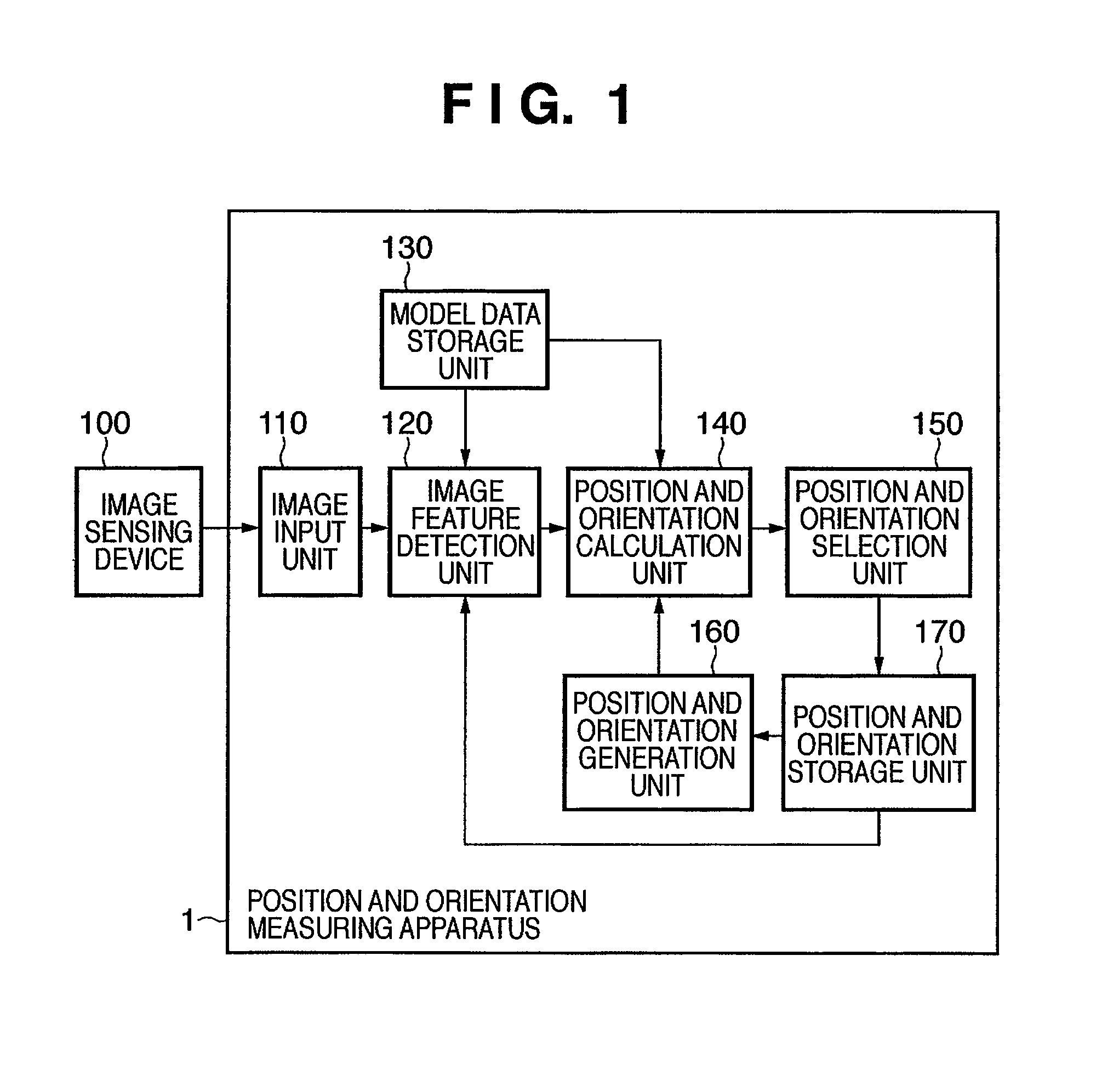
[0067]FIG. 1 is a block diagram showing the functional arrangement of a position and orientation measuring apparatus 1 according to this embodiment. As shown in FIG. 1, the position and orientation measuring apparatus 1 comprises an image input unit 110, image feature detection unit 120, model data storage unit 130, position and orientation calculation unit 140, position and orientation selection unit 150, position and orientation generation unit 160, and position and orientation storage unit 170. An image sensing device 100 is connected to the image input unit 110.
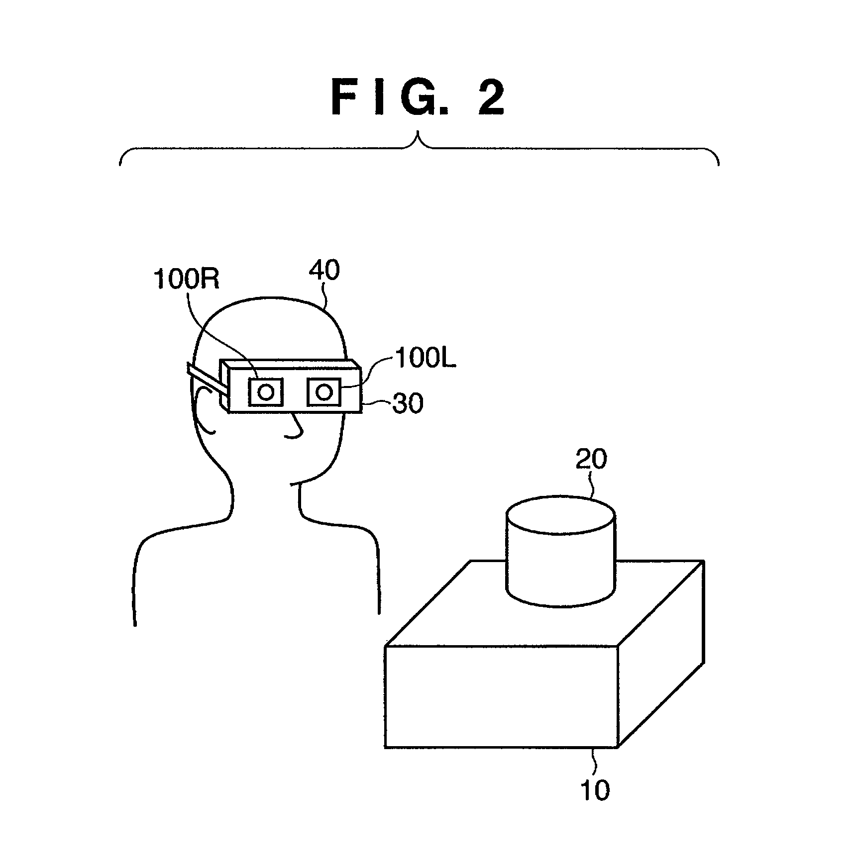
[0068]FIG. 2 illustrates a user who wears the image sensing devices 100 and a space to be observed by this user.
[0069]An observer 40 wears a video see-through HMD 30. The video see-through HMD 30 incorporates image sensing devices 100R and 100L corresponding to the right and left eyes. The image sensing devices 100R and 100L respective sense movies of the physical space. In FIG. 2, the image sensing devices 100R and 100L ...
second embodiment
[0157]In the first embodiment, a pair of position information and orientation information for each frame are stored in the position and orientation storage unit 170. In this embodiment, a plurality of pairs of position information and orientation information are stored in a position and orientation storage unit 270.
[0158]In the following description, assume that components and the like which are not especially referred to are the same as those in the first embodiment.
[0159]FIG. 10 is a block diagram showing the functional arrangement of a position and orientation measuring apparatus 2 according to this embodiment. The same reference numerals in FIG. 10 denote the same components as those in FIG. 1, and a repetitive description thereof will be avoided.
[0160]A position and orientation storage unit 270 stores a plurality of positions and orientations of the image sensing device 100L, which are calculated by the position and orientation calculation unit 140, for images of several past f...
third embodiment
[0222]Various modifications will be described below.
PUM
 Abstract
Description
Claims
Application Information