Information processing apparatus and method

a technology of information processing and image sensing device, which is applied in image data processing, wave based measurement systems, instruments, etc., can solve the problems of registration collapse, marker cannot be used, and registration is known, so as to avoid the effect of “collapse of registration” and easy and accurate calculation of the position and orientation of the image sensing devi

Inactive Publication Date: 2008-07-17
CANON KK
View PDF2 Cites 20 Cited by
  • Summary
  • Abstract
  • Description
  • Claims
  • Application Information

AI Technical Summary

Benefits of technology

[0040]The present invention has been made in consideration of the aforementioned problems, and has as its object to provide a technique for easily and accurately calculating the position and orientation of an image sensing device while avoiding “collapse of registration” that may occur upon calculating the position and orientation of the image sensing device on the physical space.

Problems solved by technology

As one of major problems to be solved upon implementing the AR technique, a problem about registration is known.
However, such markers cannot be used when it is impossible to physically allocate markers or when markers are not wanted to be allocated due to disfigurement or the like.
For this reason, for example, when the position and orientation calculations in the previous frame have failed, the position and orientation of the camera can no longer be correctly calculated in the subsequent frames, thus collapsing the registration.
Hence, upon rendering a virtual object in the AR technique, the correct position and orientation of the camera cannot always be used.
Since the scheme disclosed in non-patent references 6 and 7 requires calculations of likelihoods for several hundreds of particles, the calculation load is heavy.
For this reason, this scheme is not suitable for an AR application which requires realtimeness.
With the scheme using the particle filter, since the position and orientation of the camera are expressed as a set of particles, the obtained position and orientation of the camera are often inaccurate, and jitter is produced between frames.

Method used


Image

  • Information processing apparatus and method
  • Information processing apparatus and method
  • Information processing apparatus and method

Examples


first embodiment

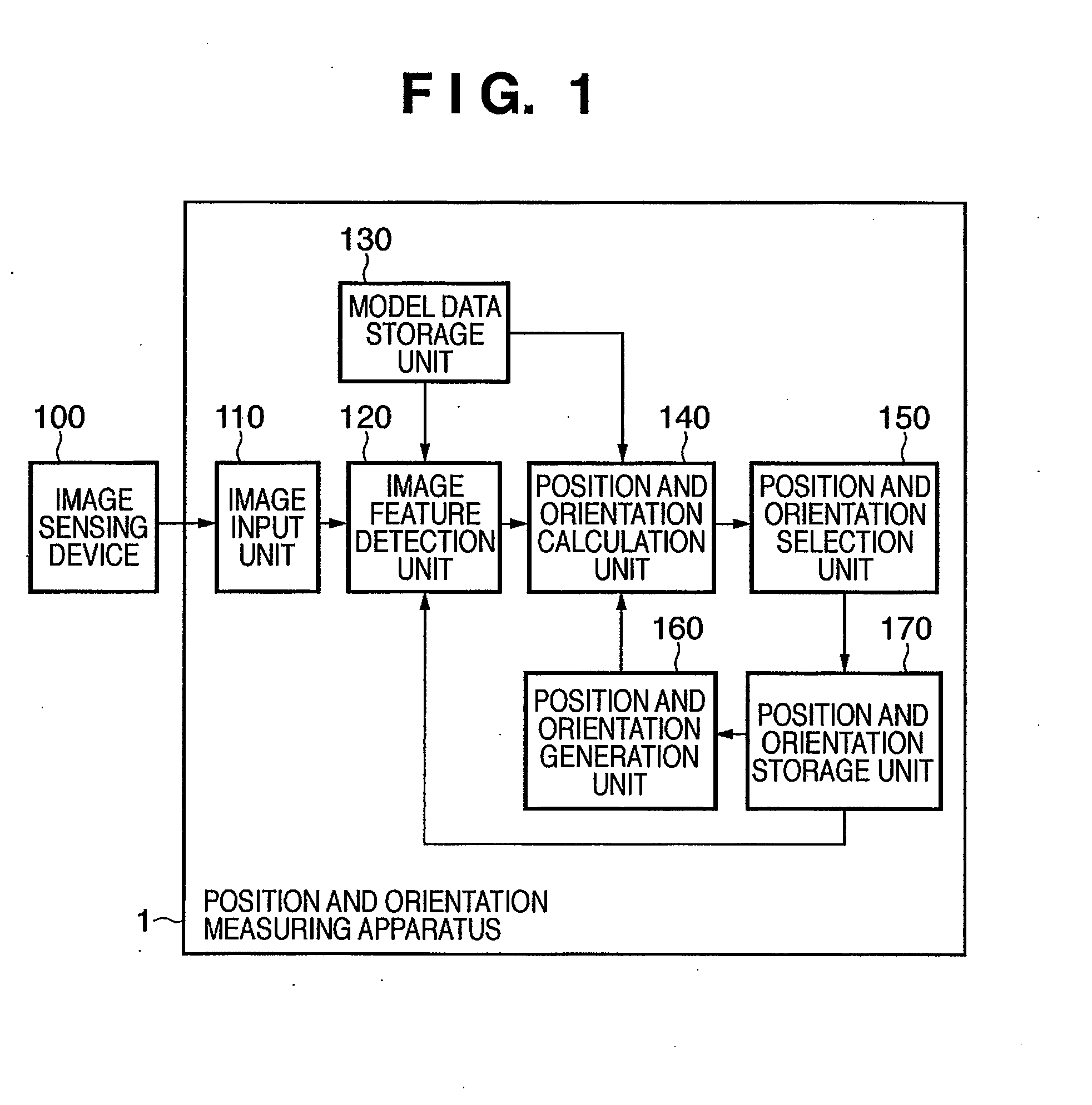
[0067]FIG. 1 is a block diagram showing the functional arrangement of a position and orientation measuring apparatus 1 according to this embodiment. As shown in FIG. 1, the position and orientation measuring apparatus 1 comprises an image input unit 110, image feature detection unit 120, model data storage unit 130, position and orientation calculation unit 140, position and orientation selection unit 150, position and orientation generation unit 160, and position and orientation storage unit 170. An image sensing device 100 is connected to the image input unit 110.

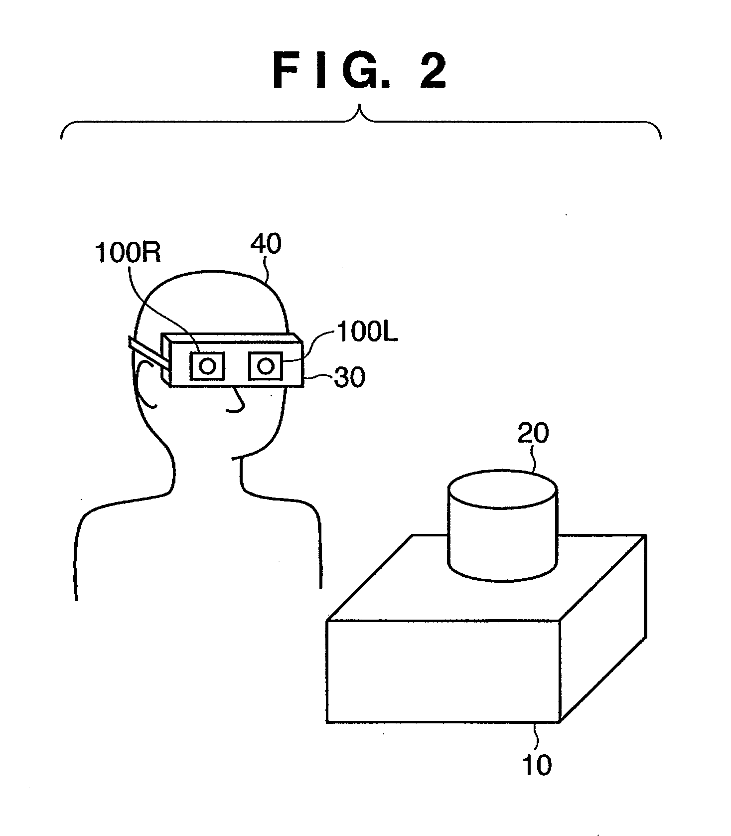
[0068]FIG. 2 illustrates a user who wears the image sensing devices 100 and a space to be observed by this user.

[0069]An observer 40 wears a video see-through HMD 30. The video see-through HMD30 incorporates image sensing devices 100R and 100L corresponding to the right and left eyes. The image sensing devices 100R and 100L respective sense movies of the physical space. In FIG. 2, the image sensing devices 100R and 100L s...

second embodiment

[0149]In the first embodiment, a pair of position information and orientation information for each frame are stored in the position and orientation storage unit 170. In this embodiment, a plurality of pairs of position information and orientation information are stored in a position and orientation storage unit 270.

[0150]In the following description, assume that components and the like which are not especially referred to are the same as those in the first embodiment.

[0151]FIG. 10 is a block diagram showing the functional arrangement of a position and orientation measuring apparatus 2 according to this embodiment. The same reference numerals in FIG. 10 denote the same components as those in FIG. 1, and a repetitive description thereof will be avoided.

[0152]A position and orientation storage unit 270 stores a plurality of positions and orientations of the image sensing device 100L, which are calculated by the position and orientation calculation unit 140, for images of several past f...

third embodiment

[0214]Various modifications will be described below.


PUM


Abstract

Three pieces of candidate position information are calculated based on a plurality of pieces of sensing position information, and three pieces of candidate orientation information are calculated based on a plurality of pieces of sensing orientation information. Sets each of which combines one candidate position information and one candidate orientation information are prepared for all combinations. For each set, the candidate position information and candidate orientation information which configure that set are corrected. An evaluation value is calculated for each corrected set, and one of the sets is selected based on the calculated evaluation values. The candidate position information and candidate orientation information which configure the selected set are respectively recorded in a memory as sensing position information and sensing orientation information.

Description

BACKGROUND OF THE INVENTION[0001]1. Field of the Invention[0002]The present invention relates to a technique for calculating the position and orientation of an image sensing device.[0003]2. Description of the Related Art[0004]In recent years, studies about an Augmented Reality (to be abbreviated as AR hereinafter) technique, which superimposes information of a virtual space in a physical space and presents a composite image to the user, have been extensively made. As an information presentation apparatus in the AR technique, a video see-through head mounted display (to be abbreviated as HMD hereinafter) is typically used. The video see-through HMD incorporates a camera which senses an image of the physical space. On the other hand, virtual objects are rendered by computer graphics (to be abbreviated as CG hereinafter) in accordance with the position and orientation of this camera in the physical space. A composite image is generated by superimposing the rendered virtual objects on t...

Claims


Application Information

Patent Timeline
Patent Type & Authority Applications(United States)
IPC IPC(8): G01C11/00
CPCG01C11/00G06T7/20G06T7/0042G01S5/16G06T7/73
Inventor KOTAKE, DAISUKEUCHIYAMA, SHINJIKATO, HIROKAZU
Owner CANON KK
Why Eureka
Try Eureka