Enclosure for a portable hemodialysis system

a hemodialysis system and enclosure technology, applied in the field of enclosures for portable hemodialysis systems, can solve the problems of large amount of dialysate needed for hemodialysis, inefficient hemodialysis, difficult and expensive,

Active Publication Date: 2013-03-12
DEKA PROD LLP
View PDF445 Cites 134 Cited by
  • Summary
  • Abstract
  • Description
  • Claims
  • Application Information

AI Technical Summary

Benefits of technology

[0005]In one aspect of the invention, an enclosure for containing a portable hemodialysis unit is provided, where the hemodialysis unit includes suitable components for performing hemodialysis including a dialyzer, one or more pumps to circulate blood through the dialyzer, a source of dialysate, and one or more pumps to circulate the dialysate through the dialyzer. The enclosure may include a housing that supports the components of the hemodialysis unit and has a front panel at which blood circuit connections and dialysate fluidic connections are located. For example, the front panel may support blood line connections for patient blood access, connections for a reagent supply, dialyzer connections for both blood flow and dialysate, etc. Thus, in one embodiment, an operator may complete all necessary fluid circuit connections for the blood circuit and reagent supply at the housing front panel. The enclosure may also include a pair of vertical, side-by-side doors hingedly mounted to the housing at opposite sides of the front panel so that the doors are movable between open and closed positions. With the doors in an open position, an operator may have access to the blood circuit connections and dialysate fluidic connections. Also, with the doors in the closed position, access to the patient access and dialysate fluidic connections may be blocked, and the doors may allow for the retention of heat in the housing suitable for disinfection during a disinfection cycle. For example, at least one of the doors may include a seal to resist air exchange between an interior and an exterior of housing when the doors are in the closed position to help retain heat and / or help resist entry of dust, dirt or other contaminants.
[0027]In another aspect of the invention, a reagent supply arrangement for a hemodialysis system may be arranged to provide two or more reagent materials for use in preparing a dialysate and may include a connector arranged to help prevent the connection of a reagent material to the wrong port. For example, the reagent supply may include an E-prong connector having three parallel prongs with two outer prongs arranged in a common plane and a center prong arranged above the common plane, a first supply line for a first reagent connected in fluid communication with one of the outer prongs, a second supply line for a second reagent connected in fluid communication with the other of the outer prongs, a liquid line connected in fluid communication with the center prong, and a container for housing the first reagent having an inlet connected to the liquid line and an outlet connected to the first supply line for the first reagent. The E-prong connector may help prevent the improper connection of the first and second supply lines to the dialysis unit, e.g., because the central prong being located out of the plane of the two outer prongs ensure connection of the E-prong connector in only one way to the dialysis unit.

Problems solved by technology

Many factors make hemodialysis inefficient, difficult, and expensive.
These factors include the complexity of hemodialysis, the safety concerns related to hemodialysis, and the very large amount of dialysate needed for hemodialysis.
Therefore any increase in the ease and efficiency of the dialysis process could have an impact on treatment cost or patient outcome.

Method used


Image

  • Enclosure for a portable hemodialysis system
  • Enclosure for a portable hemodialysis system
  • Enclosure for a portable hemodialysis system

Examples


Embodiment Construction

[0060]Various aspects of the invention are generally directed to new systems for hemodialysis and the like, such as hemofiltration systems, hemodiafiltration systems, plasmapheresis systems, etc. Accordingly, although the various systems and methods described herein are described in relation to hemodialysis, it should be understood that the various systems and method described herein are applicable to other dialysis systems and / or in any extracorporeal system able to treat blood or other bodily fluids, such as plasma.

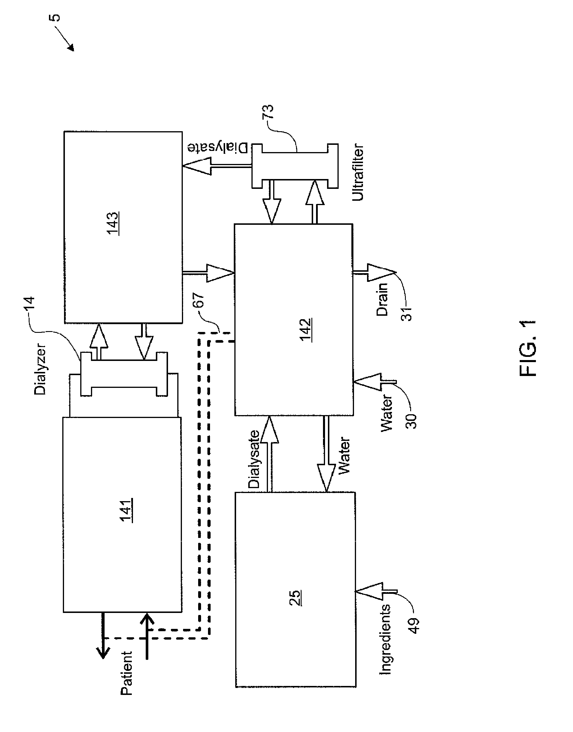
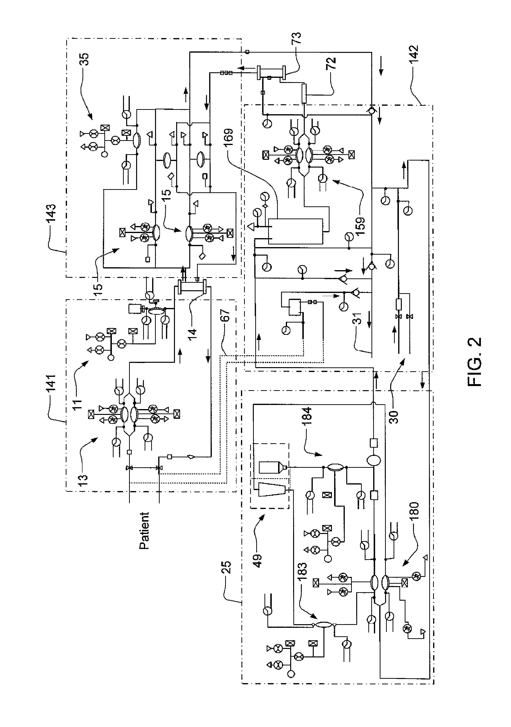
[0061]As discussed below, a hemodialysis system typically includes a blood flow path and a dialysate flow path. It should be noted that within such flow paths, the flow of fluid is not necessarily linear, and there may be any number of “branches” within the flow path that a fluid can flow from an inlet of the flow path to an outlet of the flow path. Examples of such branching are discussed in detail below. In the blood flow path, blood is drawn from a patient, and is pa...


PUM

PropertyMeasurementUnit
pore sizeaaaaaaaaaa
pore sizeaaaaaaaaaa
pore sizeaaaaaaaaaa

Abstract

An enclosure for containing a portable hemodialysis unit includes a housing suitable to support components for performing hemodialysis including a dialyzer, one or more pumps to circulate blood through the dialyzer, a source of dialysate, and one or more pumps to circulate the dialysate through the dialyzer. The housing may have a front panel at which blood circuit connections and dialysate fluidic connections are located, e.g., blood line connections for patient blood access, connections for a reagent supply, dialyzer connections for both blood flow and dialysate, etc. The enclosure may also include a pair of vertical, side-by-side doors hingedly mounted to the housing. With the doors in the closed position, access to the patient access and dialysate fluidic connections may be blocked, and the doors may allow for the retention of heat in the housing suitable for disinfection during a disinfection cycle.

Description

RELATED APPLICATIONS[0001]This application is a continuation-in-part of prior U.S. application Ser. No. 12 / 072,908, filed Feb. 27, 2008, which claims the benefit of U.S. Provisional Application Ser. No. 60 / 903,582, filed Feb. 27, 2007 and U.S. Provisional Application Ser. No. 60 / 904,024, filed Feb. 27, 2007. This application is a continuation-in-part of prior U.S. application Ser. No. 12 / 038,474, filed Feb. 27, 2008, which is a continuation-in-part of prior U.S. application Ser. No. 11 / 871,821, filed Oct. 12, 2007, which claims the benefit of U.S. Provisional Application Ser. No. 60 / 921,314, filed Apr. 2, 2007 and U.S. Provisional Application Ser. No. 60 / 904,024, filed Feb. 27, 2007. This application is a continuation-in-part of prior U.S. application Ser. No. 12 / 038,648, filed Feb. 27, 2008, which is a continuation-in-part of prior U.S. application Ser. No. 11 / 871,803, filed Oct. 12, 2007, which claims the benefit of U.S. Provisional Application Ser. No. 60 / 921,314, filed Apr. 2, 2...

Claims


Application Information

Patent Timeline
Patent Type & Authority Patents(United States)
IPC IPC(8): B01D61/28
CPCA61M1/16A61M1/14A61M1/1639A61M1/1692A61M2205/12A61M2209/08A61M1/34A61M2205/15A61M2205/3331A61M2205/3368A61M1/3403A61M1/3406A61M1/341A61M1/1601A61M2205/502A61M1/362265A61M1/362227A61M1/362263A61M1/362266A61M1/36225
Inventor GRANT, KEVIN L.DEMERS, JASON A.DALE, JAMES D.CHAWAN, ARUN D.COLLINS, DAVID E.
Owner DEKA PROD LLP
Why Eureka
Try Eureka