Chain tensioner

a tensioner and chain technology, applied in the direction of belts/chains/gearings, mechanical instruments, belts/chains/gearings, etc., can solve the problems of increasing the processing cycle time and the cost of forming the contact surfa

Active Publication Date: 2013-03-12
NTN CORP
View PDF35 Cites 0 Cited by
  • Summary
  • Abstract
  • Description
  • Claims
  • Application Information

AI Technical Summary

Benefits of technology

[0013]To achieve this object, the inventors of this invention found that deformation of the contact surface of the screw rod that contacts the rod seat can be avoided by providing an intermediate portion having a diameter smaller than the root diameter of the external thread on the outer circumference of the portion of the screw rod protruding from the plunger and forming the contact surface on the axial end face of the intermediate portion. This is because the flow of material is absorbed by the intermediate portion when the external thread is rolled on the outer circumference of the screw rod after forging the contact surface. Thus, the contact surface of the screw rod that contact the rod seat can be formed by forging with the possibility of deformation.
[0014]Preferably a chamfer tapering from the end of the external thread to the intermediate portion is provided on the outer circumference of the screw rod. With this configuration, a rolling die is led in smoothly, thereby rolling the external thread with high accuracy.
[0015]When forming a spring receiving hole in the screw rod so as to receive one end of the return spring, the spring receiving hole can be formed by forging. In this case, thickness of the screw rod from the root of the external thread to the inner face of the spring receiving hole is preferably not smaller than twice the height of the external thread. This maintains rigidity of the screw rod when rolling the external thread, thereby maintaining roundness of the screw rod during rolling.

Problems solved by technology

However, it increases the processing cycle time and the cost to form the contact surface 43, spring receiving hole 44 and oil path hole 45 by machining.

Method used


Image

  • Chain tensioner
  • Chain tensioner
  • Chain tensioner

Examples


Embodiment Construction

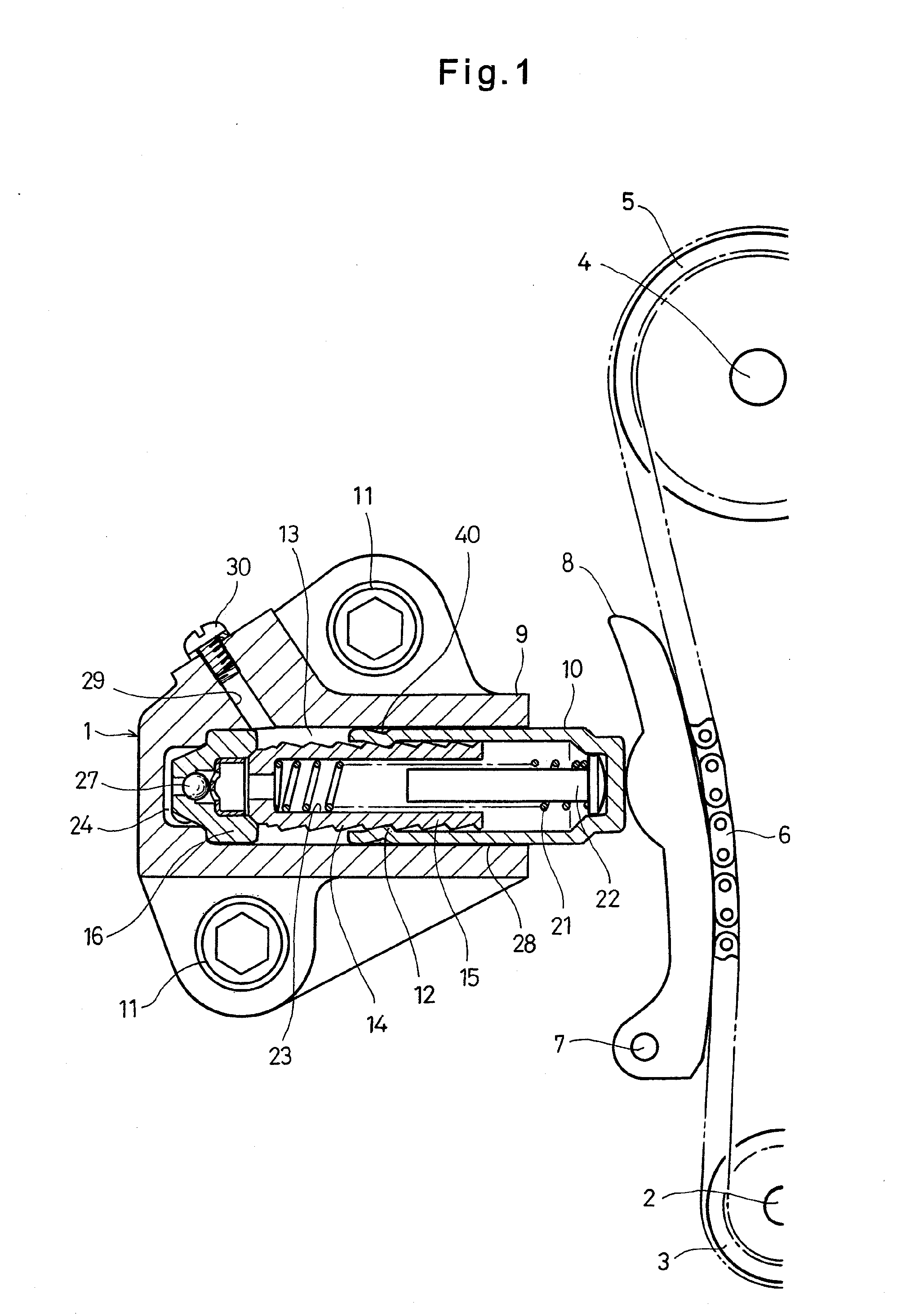
[0043]FIG. 1 shows a chain transmission device mounted with a chain tensioner 1 according to the embodiment of this invention. This chain transmission device includes a sprocket 3 fixed on a crankshaft 2 of an engine, a sprocket 5 fixed on a camshaft 4, and a chain 6 coupling the sprockets 3 and 5 together for transmitting rotation of the crankshaft 2 to the camshaft 4. Valves (not shown) of combustion chambers are opened and closed by the rotation of the camshaft 4.

[0044]A chain guide 8 pivotably supported around a pivot shaft 7 contacts the chain 6. The chain tensioner 1 presses the chain 6 through the chain guide 8.

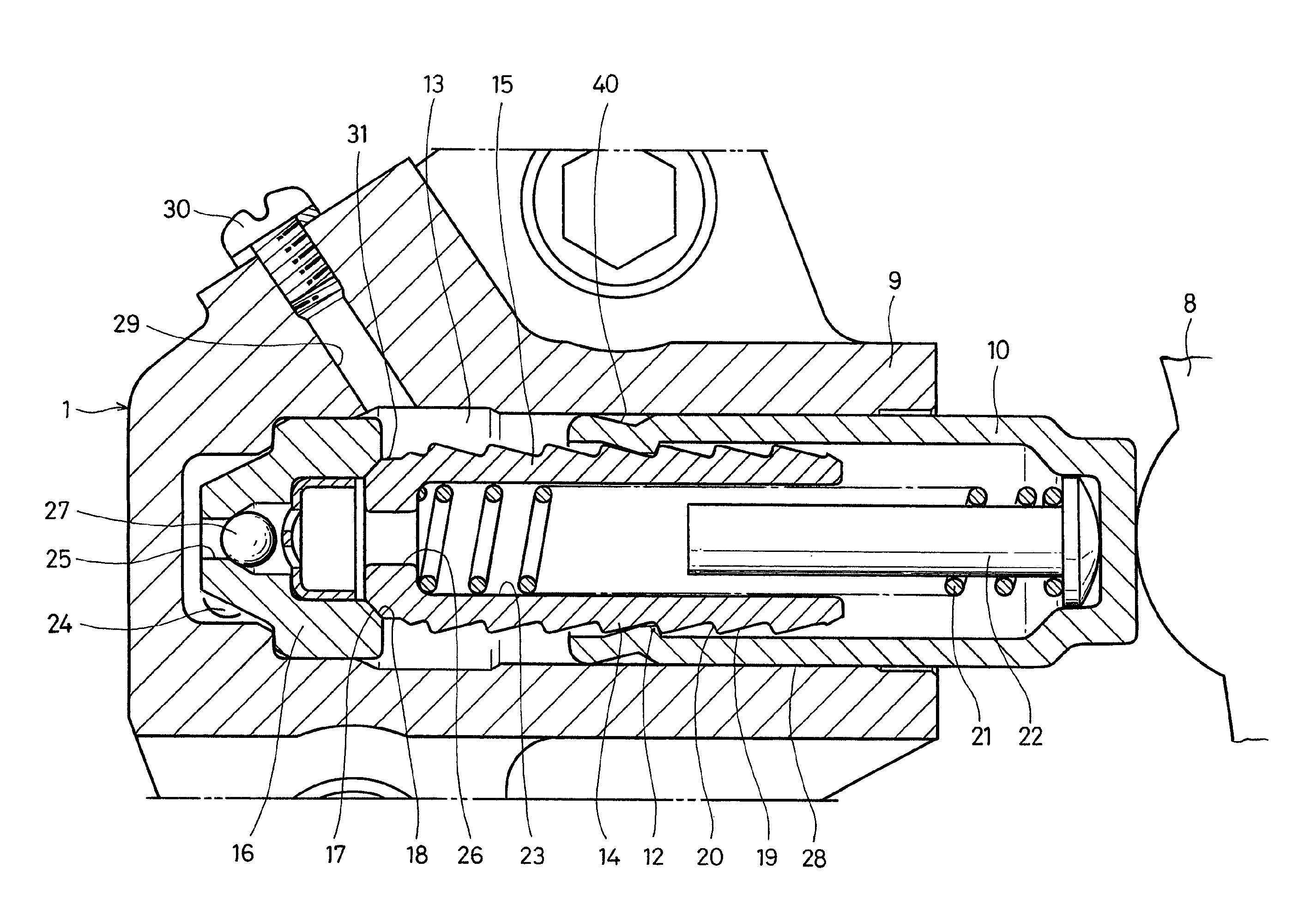
[0045]The chain tensioner 1 comprises a cylindrical cylinder 9 having an open end and a closed bottom at the other end, and a cylindrical plunger 10 axially slidably inserted in the cylinder 9. The cylinder 9 is fixed to an engine block (not shown) with bolts 11.

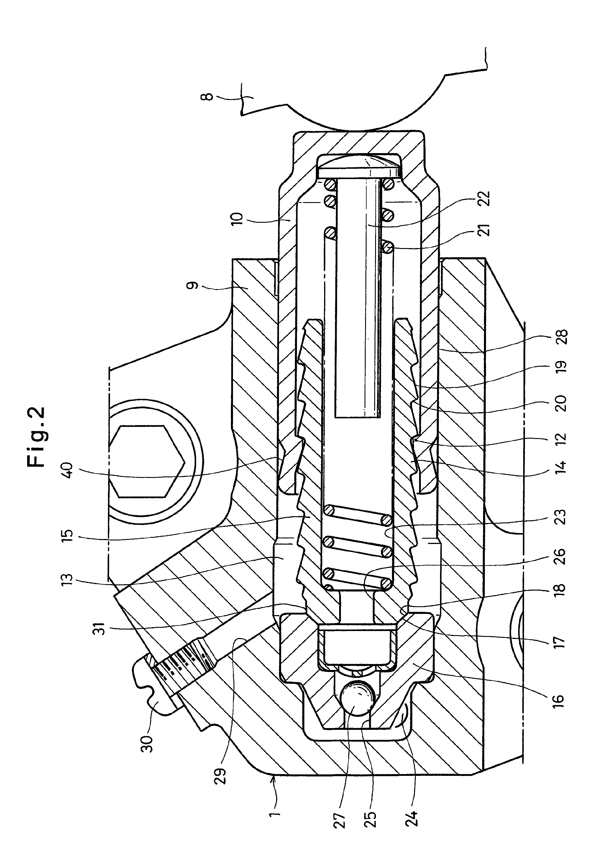
[0046]As shown in FIG. 2, the plunger 10 has a closed end protruding from the cylinder 9 and abutting agains...


PUM


Abstract

A chain tensioner includes a cylinder having a closed end, an internally threaded plunger axially slidable in the cylinder, a return spring biasing the plunger in the protruding direction from the cylinder, and a screw rod having an external thread in threaded engagement with the internal thread of the plunger. The portion of the screw rod protruding from the plunger abuts a rod seat provided in the cylinder. The screw rod has a rolled external thread and an intermediate portion protruding from the plunger and having an outer diameter smaller than the diameter of the root of the external thread. The screw rod has a forged contact surface, to be contacted with the rod seat, on the axial end face of the intermediate portion. The internal thread may be formed by pressing, and a pressed recess, corresponding to the internal thread, may be formed on the plunger's outer circumference.

Description

BACKGROUND OF THE INVENTION[0001]This invention relates to a chain tensioner used for maintaining tension of a timing chain that drives a camshaft of a vehicle engine.[0002]Generally in an automobile engine, rotation of a crankshaft is transmitted to a camshaft through a timing chain, thereby opening and closing valves of combustion chambers by rotation of the camshaft. In many cases, to keep the tension of the chain within appropriate range, a tension adjustment device is used which comprises a chain guide provided pivotably around a support shaft and a chain tensioner pushing the chain guide toward the chain.[0003]As a chain tensioner incorporated in this tension adjustment device, a chain tensioner is known comprising a cylinder having open and closed ends, a plunger axially slidably inserted in the cylinder, and a return spring biasing the plunger in the protruding direction from the cylinder. The plunger has an open end inserted in the cylinder and a closed end and is formed wi...

Claims


Application Information

Patent Timeline
Patent Type & Authority Patents(United States)
IPC IPC(8): F16H7/22F16H7/08
CPCF16H7/0836F16H7/0848F16H2007/0806F16H2007/0812F16H2007/0857F16H2007/0859
Inventor SATO, SEIJIKITANO, SATOSHIHAYAKAWA, HISASHIFURUKAWA, TASUKU
Owner NTN CORP
Why Eureka
Try Eureka