Map matching for security applications

a mapping and object technology, applied in the field of object position data calculation, can solve the problems of not being able to provide any information, not always allowing, limited to the direct field of vision of the vehicle, etc., and achieve the effect of improving the alignment of a measured position

Inactive Publication Date: 2013-03-19
CONTINENTAL TEVES AG & CO OHG
View PDF13 Cites 12 Cited by
  • Summary
  • Abstract
  • Description
  • Claims
  • Application Information

AI Technical Summary

Benefits of technology

[0098]It is thus possible to use the apparatus and align data even when operation of the GPS receiver is interrupted, for example because the signal has broken off in a tunnel or under a bridge. This module can also make a decision without GPS information if, during this time without a connection, no other roads cross, which is normally the case in tunnels. This module therefore provides the system with the option of “compound navigation” (also called Dead Reckoning). This is a further significant advantage of the invention.
[0099]An example of how this module weighs up two possible positions is shown in FIG. 6. Here, the two vehicles shown represent the two possible positions, and dn+11 corresponds to the estimate of the next distance covered. This module is complex in terms of computation, because the minimum distance to each possible road point needs to be calculated backwards, since there may be different paths from a point A to another point B and all of them need to be analyzed. The estimated covered distance is now calculated using a Kalman filter, for example. If the map matching is used in motor vehicles, however, the accuracy can be significantly increased by this module, because the vehicle sensors can be used to estimate this covered distance and not the derived information from the GPS, as in the case of the Kalman filter. A further Kalman filter which uses vehicle sensors should then be implemented in order to calculate these covered distances.
[0100]FIG. 2 shows a digital map 102 which shows a measured position for a vehicle 101 which cannot match with the infrastructure of the map shown. According to the measured positions, the vehicle 200 is situated within a building 203. In this situation, the inventive apparatus and the inventive process can use the fast exclusion filter function and can use the combination of various methods for calculating and assessing the various cartography elements in order to determine the actual position of the vehicle. In this context, the precise determination can also be effected iteratively and with a control loop. In addition, exemplary cartography elements 204, roads and buildings are shown.
[0101]FIG. 2 also shows the new aligned position 201 after the destination cartography element 115 has been selected. This corresponds to the new aligned position of the vehicle 201. In addition, FIG. 2 shows possible calculation of the new aligned position 202 by means of vectorial representation of segments and routes covered by the vehicle.
[0102]FIG. 3 shows the induced error in the case in which the secondary computation unit performs the method of an angle module. On the basis of a current position 301 for a segment direction or road direction 302 and the current route of the vehicle 304, it is possible to represent the value v ΔT 305 as shown. In this case, an angle between the road vector and the segment vector 300 is indicated. The induced error 303 during the next time interval is shown at the right-hand border of the figure as a height of the triangle.
[0103]FIG. 4 shows a graphical representation of the function of the fast exclusion filter or the computation unit. In this case, the computation unit is designed to make a first selection of cartography elements on the map on the basis of the measured position and on the basis of a predefined error. In other words, the algorithm 400 for the fast exclusion of segments or elements of a map is shown. In this case, a square area 402 with the boundaries 401 is shown. The maximum error Dmax 403, which is shown as the radius of a circle, describes the area around the measured position 101 which must contain the admissible segments. In this case, segments which have been picked out correctly 404 and segments which have not been picked out even though they do not meet the ideal filter condition of the maximum distance Dmax 405 are shown. Segments 406 which have correctly not been sorted out are likewise shown. In this context, it should again be pointed out that the term cartography element means nodes, segments, paths and loops.

Problems solved by technology

This forecast capability has previously been provided by various types of sensors, radar systems or cameras, but these are all limited to the direct field of vision of the vehicle.
This means that they are not able to provide any information about what happens after a bend, for example.
The GPS or another positioning system has an error which does not always allow a position to be indicated accurately on a road.
Furthermore, a map may also always have some accuracy errors and discrepancies from the actual cartography, which makes the position-finding directly on a road more difficult or even impossible.

Method used


Image

  • Map matching for security applications
  • Map matching for security applications
  • Map matching for security applications

Examples


Embodiment Construction

[0068]In the descriptions of the figures which follow, the same reference numerals are used for the same or similar elements.

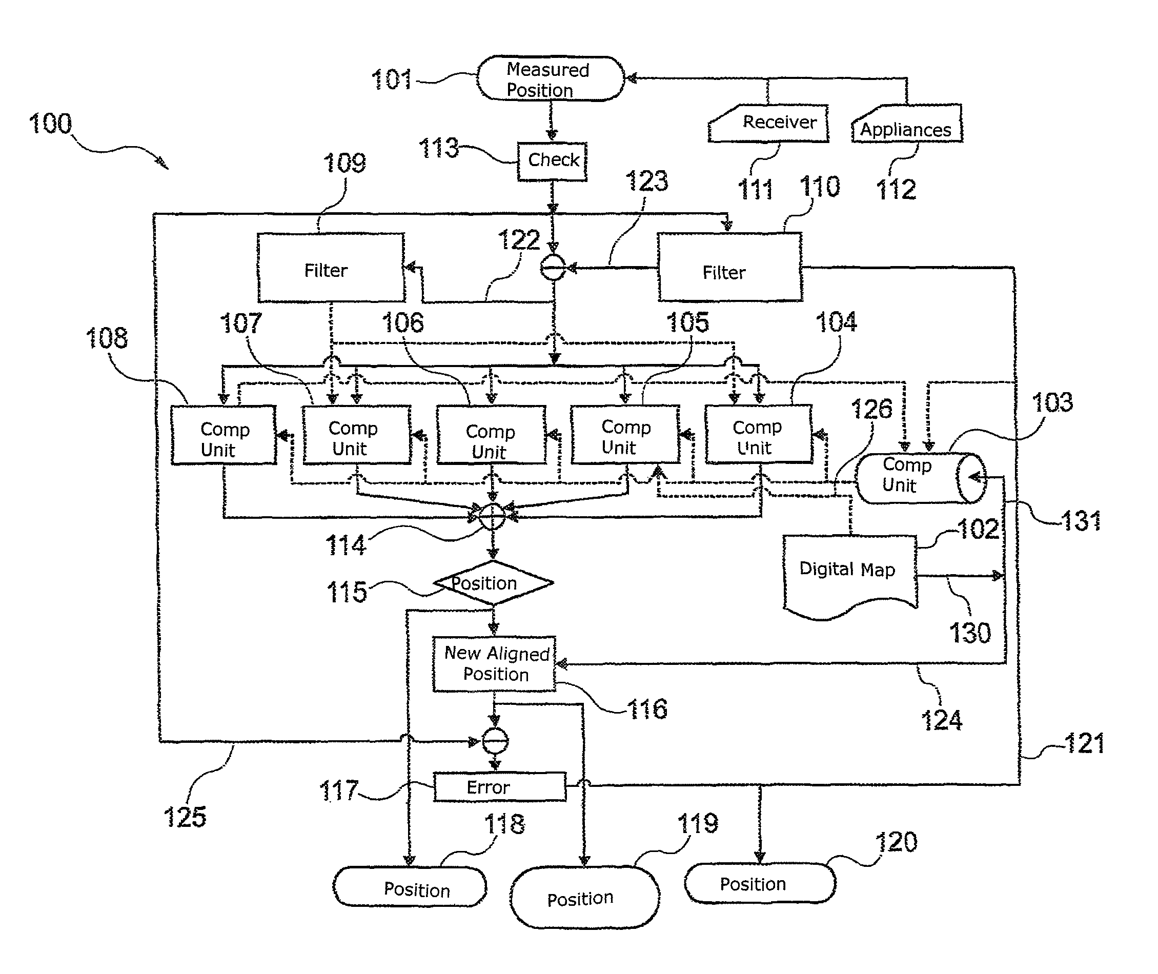
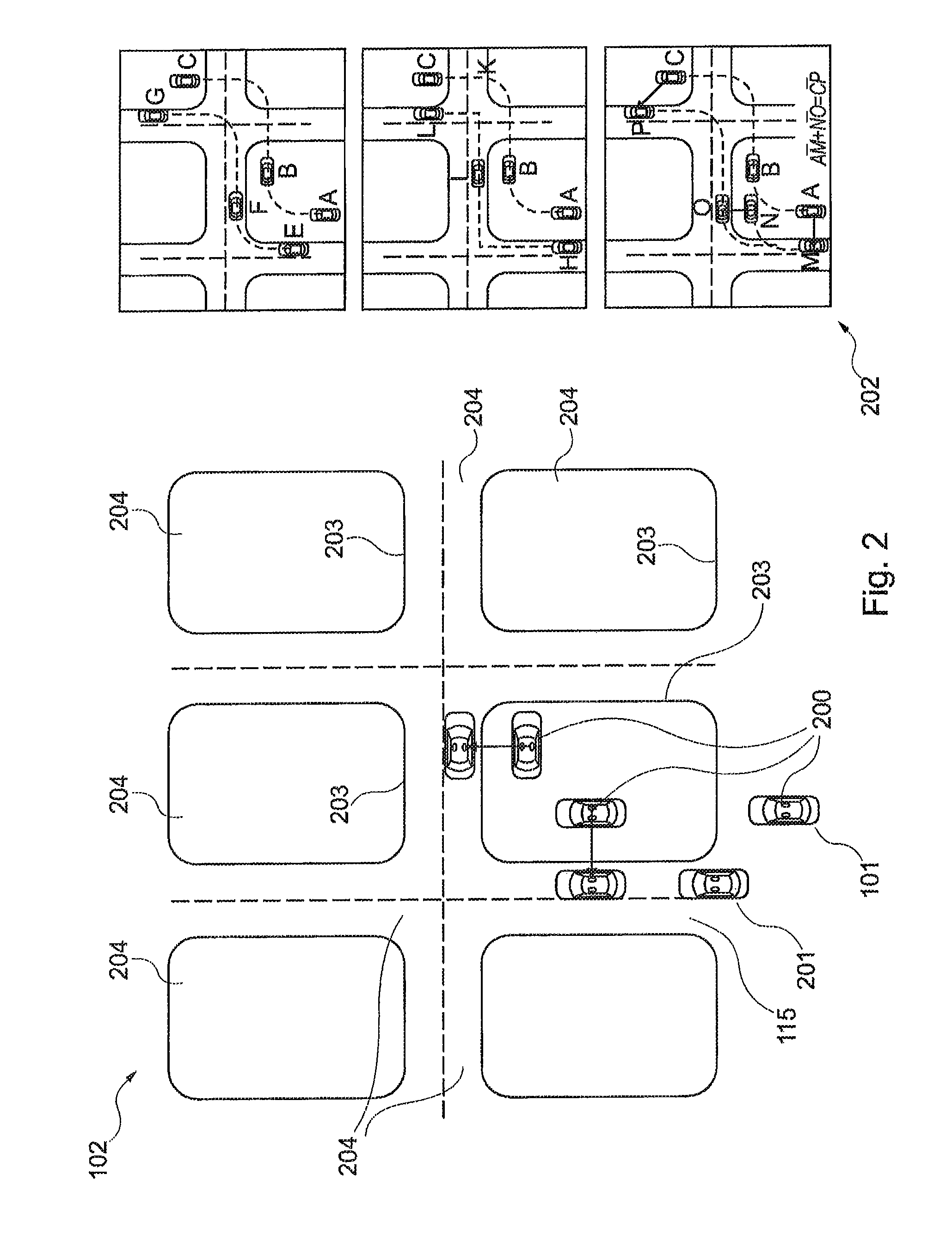
[0069]FIG. 1 shows an apparatus 100 for aligning a measured position 101 for an object with information on a digital map 102. The information on the map may be provided by cartography elements and corresponding data, for example. In addition, a computation unit 103, which may also be in the form of a fast exclusion filter, is provided. In this case, the digital map 102 provides the information stored in it, such as the information about positions of various cartography elements, for the computation unit 103. This is illustrated by the arrows 130, 131. Similarly, this information can be passed directly to the secondary computation units 104, 105, 106, 107 and 108, which is shown by way of example by the arrow 126.

[0070]To eliminate unusable cartography elements, the computation unit 103 performs one of several possible algorithms, which selects the suitable car...


PUM


Abstract

An apparatus for map matching between a measured position for an object and information on a digital map is specified. This involves a computation unit being used to perform a first selection of cartography elements on the map on the basis of the measured position and on the basis of a predefined error. In addition, the computation unit is designed to provide the selected cartography elements for a first and a second secondary computation unit. In addition, values from the secondary computation units are converted in the same unit of measurement.

Description

CROSS REFERENCE TO RELATED APPLICATIONS[0001]This application is a continuation application of application Ser. No. 12 / 601,889, filed Nov. 25, 2009, which is a the U.S. national phase application of PCT international Application No. PCT / EP2008 / 055850, filed May 13, 2008, which claims priority to German Patent Application No. 102007025065.9, filed May 29, 2007 and German Patent Application No. 102008023242.4, filed May 13, 2008, the contents of such applications being incorporated by reference herein.FIELD OF THE INVENTION[0002]The invention relates to the calculation of position data for an object. In particular, the invention relates to an apparatus for aligning a measured position for an object with information on a digital map, for a system, to the use of an apparatus, to a vehicle, to a process, to a program element and to a computer-readable medium.BACKGROUND OF THE INVENTION[0003]Safety-relevant vehicle assistance systems need to be capable of predicting dangerous situations w...

Claims


Application Information

Patent Timeline
Patent Type & Authority Patents(United States)
IPC IPC(8): G06K9/00
CPCG01C21/30
Inventor STAHLIN, ULRICHMINOVES, MARTIKEIL, ANSELM
Owner CONTINENTAL TEVES AG & CO OHG
Why Eureka
Try Eureka