Door closer with buffer mechanism for a sliding door

a buffer mechanism and door closer technology, applied in the field of door closers, can solve the problems of high cost of the production of each door closer, damage to the door panel or the doorframe, and difficult assembly process, and achieve the effect of efficient production and assembly

Inactive Publication Date: 2013-03-26
TSAI PATRICK
View PDF16 Cites 48 Cited by
  • Summary
  • Abstract
  • Description
  • Claims
  • Application Information

AI Technical Summary

Benefits of technology

[0008]The main object of the present invention is to provide a door closer fo

Problems solved by technology

However, the door panel easily bumps against a doorframe if the door panel is slammed and that results in a big noise and causes the door panel or

Method used


Image

  • Door closer with buffer mechanism for a sliding door
  • Door closer with buffer mechanism for a sliding door
  • Door closer with buffer mechanism for a sliding door

Examples


Embodiment Construction

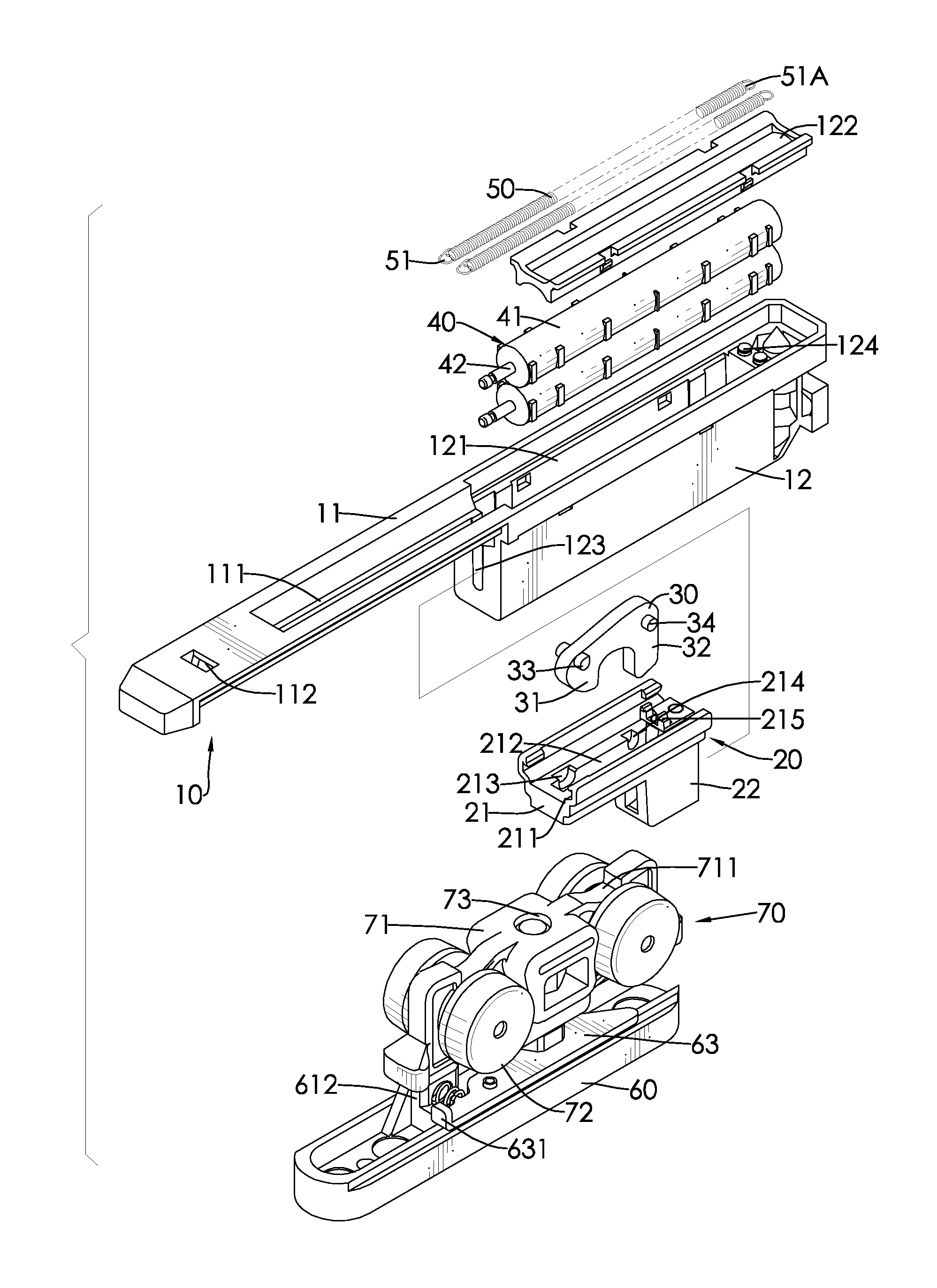
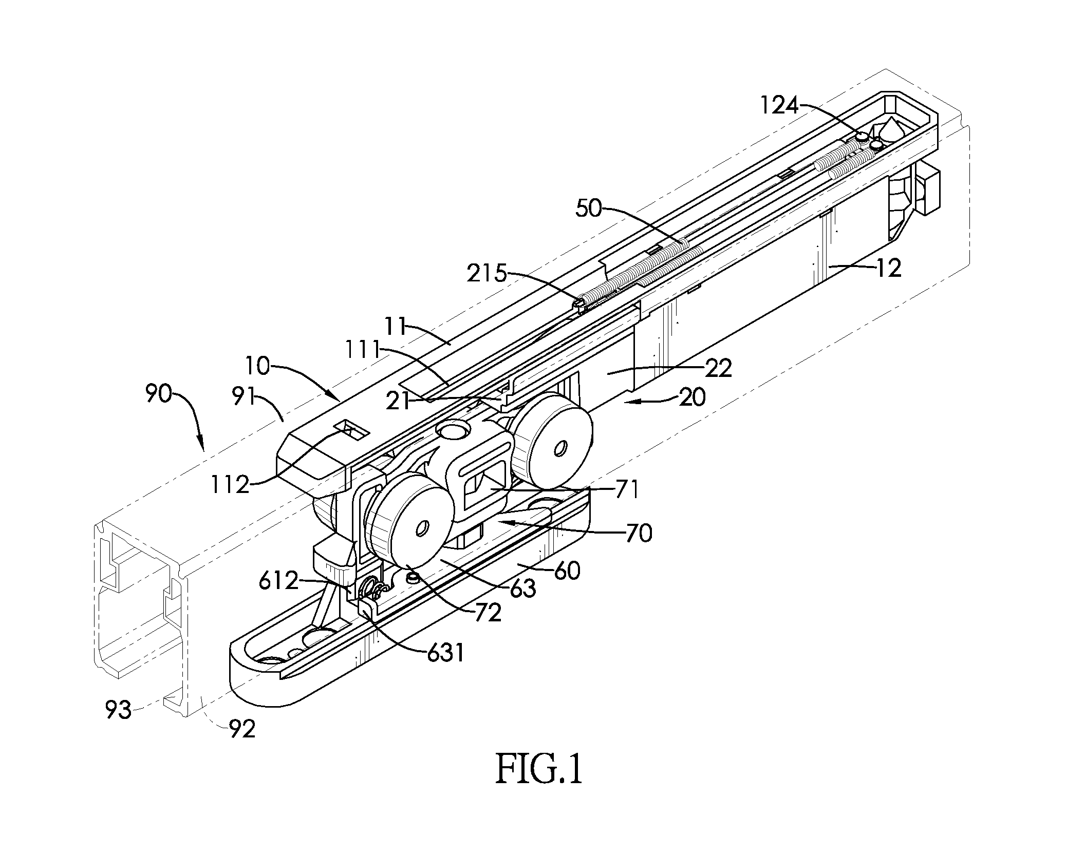
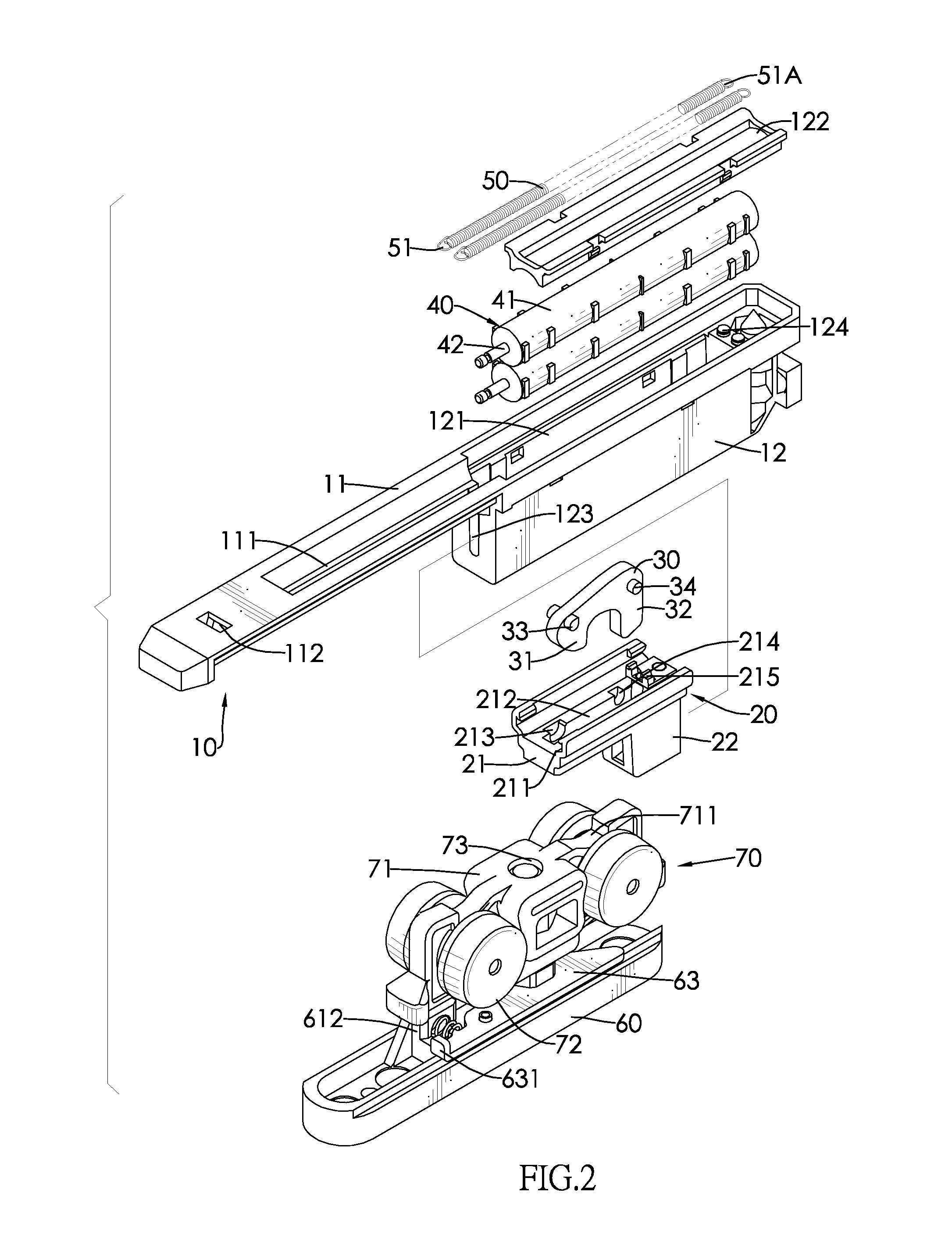
[0018]With reference to FIGS. 1 to 3, a door closer for a top hung sliding door in accordance with the present invention comprises a buffer mechanism and a trolley hanger. The buffer mechanism includes a stationary base 10, a sliding block 20, a hook 30, two buffers 40 and two resilient members 50. The trolley hanger includes a sliding base 60 and a trolley 70.

[0019]The stationary base 10 is elongated and has a front portion and a rear portion. The front portion is a guide rail 11 and the rear portion is a mounting seat 12. The guide rail 11 is a board and has an elongated hole 111 and a locking hole 112. The elongated hole 111 is formed longitudinally through the guide rail 11. The locking hole 112 is formed through the guide rail 11 and is positioned in front of the elongated hole 111. The mounting seat 12 is a block and has a front surface, a top surface, a tank 121, a cover 122 and an aperture 123. The tank 121 is formed longitudinally in the top surface of the mounting seat 12,...


PUM


Abstract

A door closer for a top hung sliding door has a buffer mechanism and a trolley hanger. The buffer mechanism includes a stationary base, a sliding block, a hook, two buffers and two resilient members. The sliding block is slidably mounted on the stationary base. The hook is pivotally mounted on the sliding block. The buffers are mounted on the stationary base and each buffer has a piston rod secured to the sliding block. The resilient members are mounted on the stationary base and each resilient member has one end secured to the sliding block. The trolley hanger has at least one engaging recess selectively engaging the hook. Therefore, the buffers can provide a buffering force and the resilient members can release a resilient force to reduce a moving speed of a door panel.

Description

BACKGROUND OF THE INVENTION[0001]1. Field of the Invention[0002]The present invention relates to a door closer, and more particularly to a door closer for a top hung sliding door that provides for efficient production and assembly.[0003]2. Description of the Prior Arts[0004]A sliding door opens by sliding, whereby a door panel is mounted on a track. Types of sliding doors include top hung sliding doors. The top hung sliding door has a door panel suspended from a track at a top edge and thereby the door panel can be easily moved. However, the door panel easily bumps against a doorframe if the door panel is slammed and that results in a big noise and causes the door panel or the doorframe to be damaged.[0005]A door closer is mounted between the top edge of the door panel and the track to reduce the moving speed of the door panel and to keep the door panel and the doorframe from being damaged. A conventional door closer comprises a buffer mechanism and a trolley hanger. The buffer mech...

Claims


Application Information

Patent Timeline
IPC IPC(8): E05F3/00E05F1/00
CPCE05F3/18E05F5/003E05D15/063E05Y2900/132E05F1/16Y10T16/27E05Y2600/528E05Y2201/412E05Y2800/21Y10T16/56Y10T16/61E05F3/227
Inventor TSAI, PATRICK
Owner TSAI PATRICK
Why Eureka
Try Eureka