
Methods and apparatus for vibration damping in a cooking device

a technology of vibration damping and cooking device, which is applied in the field of cooking device, can solve the problems of limited range of motion of moving parts, adversely affecting the desirability, functionality and/or safety of the cooking device, and achieve the effect of reducing vibration and facilitating the rotation of the rotatable food bask

Inactive Publication Date: 2013-03-26
SPINFRY
View PDF88 Cites 5 Cited by
  • Summary
  • Abstract
  • Description
  • Claims
  • Application Information

AI Technical Summary

Benefits of technology

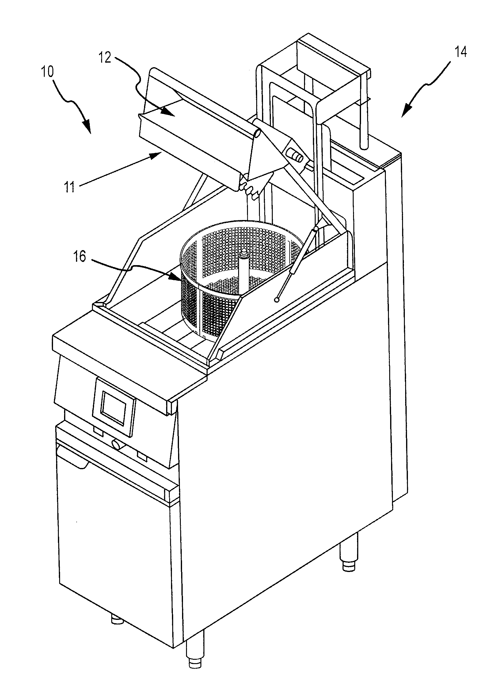
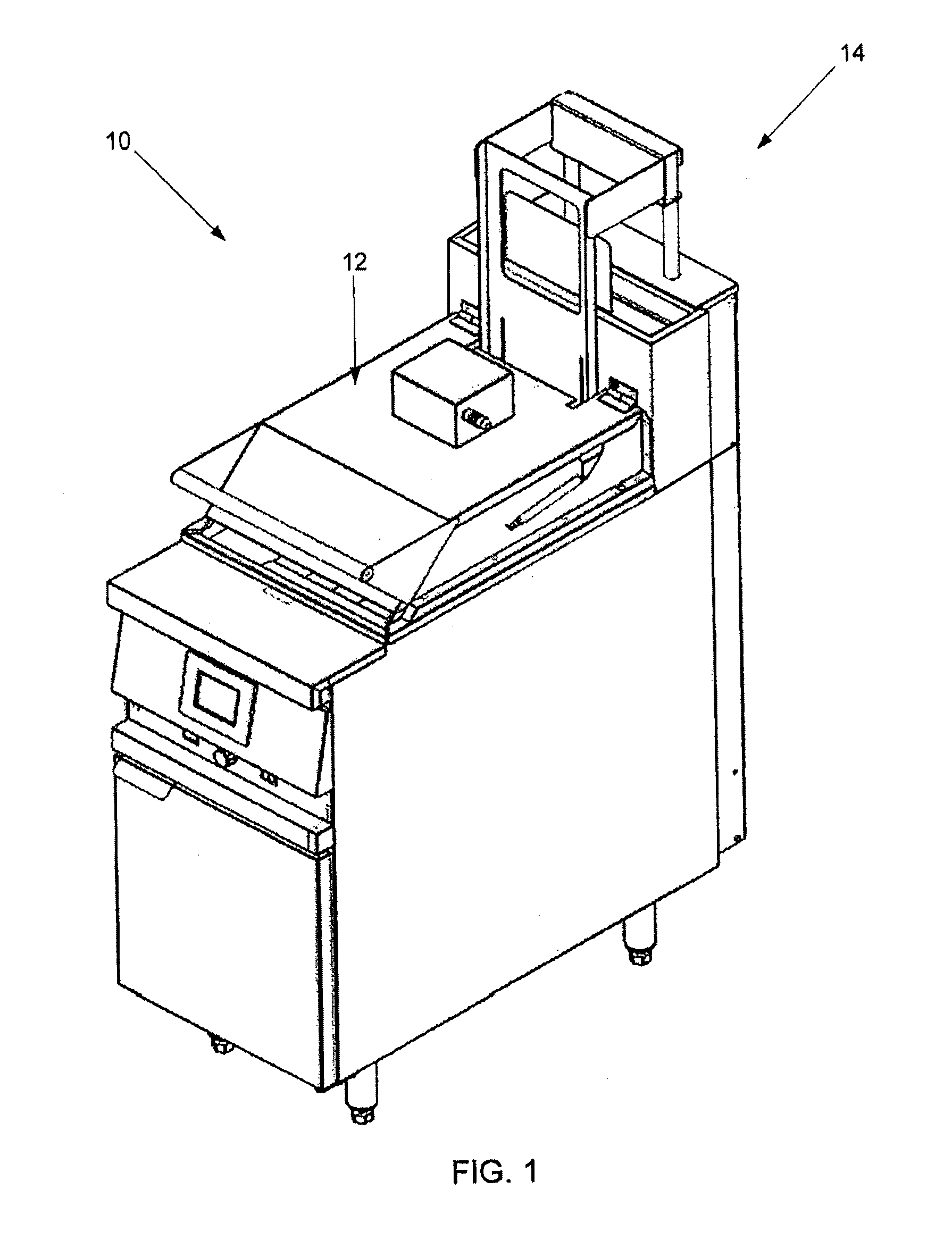
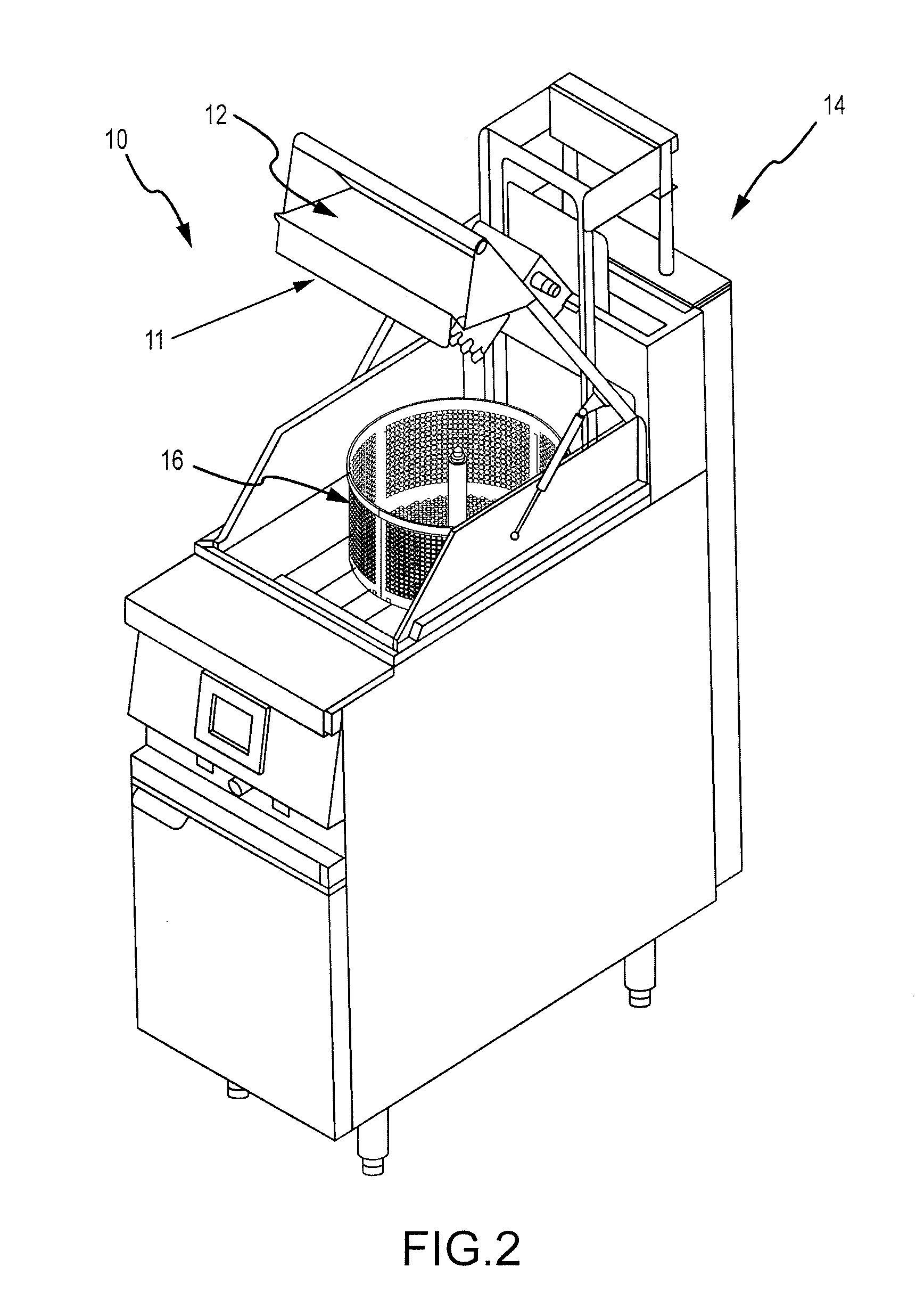
The present invention is a cooking device that reduces vibration caused by the rotating food basket. It includes a partition in the basket to keep the food evenly distributed. The device also has a motor and a lifting mechanism to move the basket between a cooking section and a spinning section. The hood helps to reduce energy consumption by about 13% compared with an open bay cooking device without the hood. The device also has a frame and a damping mechanism to absorb energy and reduce vibration caused by the rotating food basket. The damping mechanism can be coupled to the drive mechanism to further reduce vibration.

Problems solved by technology

In conventional cooking devices, any moving parts generally do not move in a fashion that creates circumstances giving rise to substantial vibration or vibratory actions because in such conventional cooking devices, the range of motion of the moving parts is limited.
For example, in a conventional deep fryer, the moving parts are limited to loading, lowering, and raising the basket or container holding the food being fried.
The vibratory actions may adversely effect the desirability, functionality, and / or safety of the cooking device.

Method used


Image

  • Methods and apparatus for vibration damping in a cooking device
  • Methods and apparatus for vibration damping in a cooking device
  • Methods and apparatus for vibration damping in a cooking device

Examples


Embodiment Construction

[0079]The detailed description herein makes use of various embodiments to assist in disclosing the present invention. While these embodiments are described in sufficient detail to enable those skilled in the art to practice the invention, it should be understood that other embodiments may be realized and that modifications of structures, arrangements, applications, proportions, elements, materials, or components used in the practice of the present invention, in addition to those not specifically recited, can be varied or otherwise particularly adapted to specific environments, manufacturing specifications, design parameters or other operating requirements without departing from the scope of the present invention and are intended to be included in this disclosure. Thus, the detailed description herein is presented for purposes of illustration only and not of limitation.

[0080]In accordance with various embodiments of the present invention, systems, methods and apparatuses for cooking ...


PUM


Abstract

A cooking device comprises a rotatable food basket disposed within the cooking device and a damping mechanism configured to reduce a vibration generated by the rotatable food basket rotating within the cooking device. An aspect of the cooking device includes a basket partition in the rotatable food basket, and the basket partition is configured to maintain a substantially equal distribution of a food within the rotatable food basket. The cooking device includes a motor in a hood for rotating the rotatable food basket, and it further includes a lifting plate and a lifting mechanism operable to move the rotatable food basket between a cooking section and a spinning section. The cooking device may also comprises a first basket portion and a second basket portion configured to be disposed within a first section and a second section of the rotatable food basket. The hood of the cooking device may also comprise a motor gear that includes a plurality of teeth configured to receive a motor key on a central shaft of the rotatable food basket. The motor key may be configured to automatically seat with the plurality of teeth in the motor gear via an electromagnetic coupling in response to an instruction from a microprocessor controller.

Description

CROSS REFERENCE TO RELATED APPLICATIONS[0001]This application is a non-provisional of U.S. Provisional Ser. No. 61 / 175,703 filed May 5, 2009 and U.S. Provisional Ser. No. 61 / 146,859, filed on Jan. 23, 2009. This application is also a continuation-in-part and claims priority to U.S. Ser. No. 12 / 193,618, filed on Aug. 18, 2008, which is a non-provisional of U.S. Ser. No. 61 / 044,733, filed on Apr. 14, 2008. This application is also a continuation-in-part and claims priority to U.S. Ser. No. 12 / 193,615, filed on Aug. 18, 2008. Further, this application is also a continuation-in-part and claims priority to PCT / US2009 / 040451 filed Apr. 14, 2009. The entirety of all of the above applications are hereby incorporated herein by reference.FIELD OF THE INVENTION[0002]The present invention relates to a cooking device, and, for example, to vibration damping in a centrifugal cooking device, a dual bay cooking device, tube heating in a cooking device, and electromagnetic coupling for a centrifugal ...

Claims


Application Information

Patent Timeline
Patent Type & Authority Patents(United States)
IPC IPC(8): A47J37/10A47J37/12
CPCA47J36/00A47J37/1204A47J37/1223A47J37/1276
Inventor FOSTER, PAUL LINCOLNTHORNOCK, DEL MOFFATMILLIKIN, RORY C. P.
Owner SPINFRY
Learn More