
Hybrid-luminescent munition projectiles

a technology of projectiles and hybrid materials, applied in the field of hybrid materials of luminescent materials used in ammunition projectiles, can solve the problems of tracer making them fire hazards, environmental and hazardous materials problems, lack of precision, etc., and achieve the effect of few known hazardous effects

Active Publication Date: 2013-03-26
UNIVERSITY OF LOUISIANA AT LAFAYETTE
View PDF29 Cites 40 Cited by
  • Summary
  • Abstract
  • Description
  • Claims
  • Application Information

AI Technical Summary

Benefits of technology

The patent describes a special type of projectile that has a feature that lets the shooter know when they have hit their target. This helps the shooter to make adjustments and improve their accuracy.

Problems solved by technology

These shortcomings include:1. The incendiary nature of energetic tracers makes them a fire hazard.
The fires can be a safety hazard in training areas and can be an undesirable consequence in battle.2. The tracers lose mass in flight, creating an inherent inaccuracy and lack of precision.3. The material used for energetic tracers creates environmental and hazardous material problems.4. The energetic tracers are difficult to manufacture.5. Energetic tracers are bi-directional; meaning they can be seen by the shooter as well as the enemy.
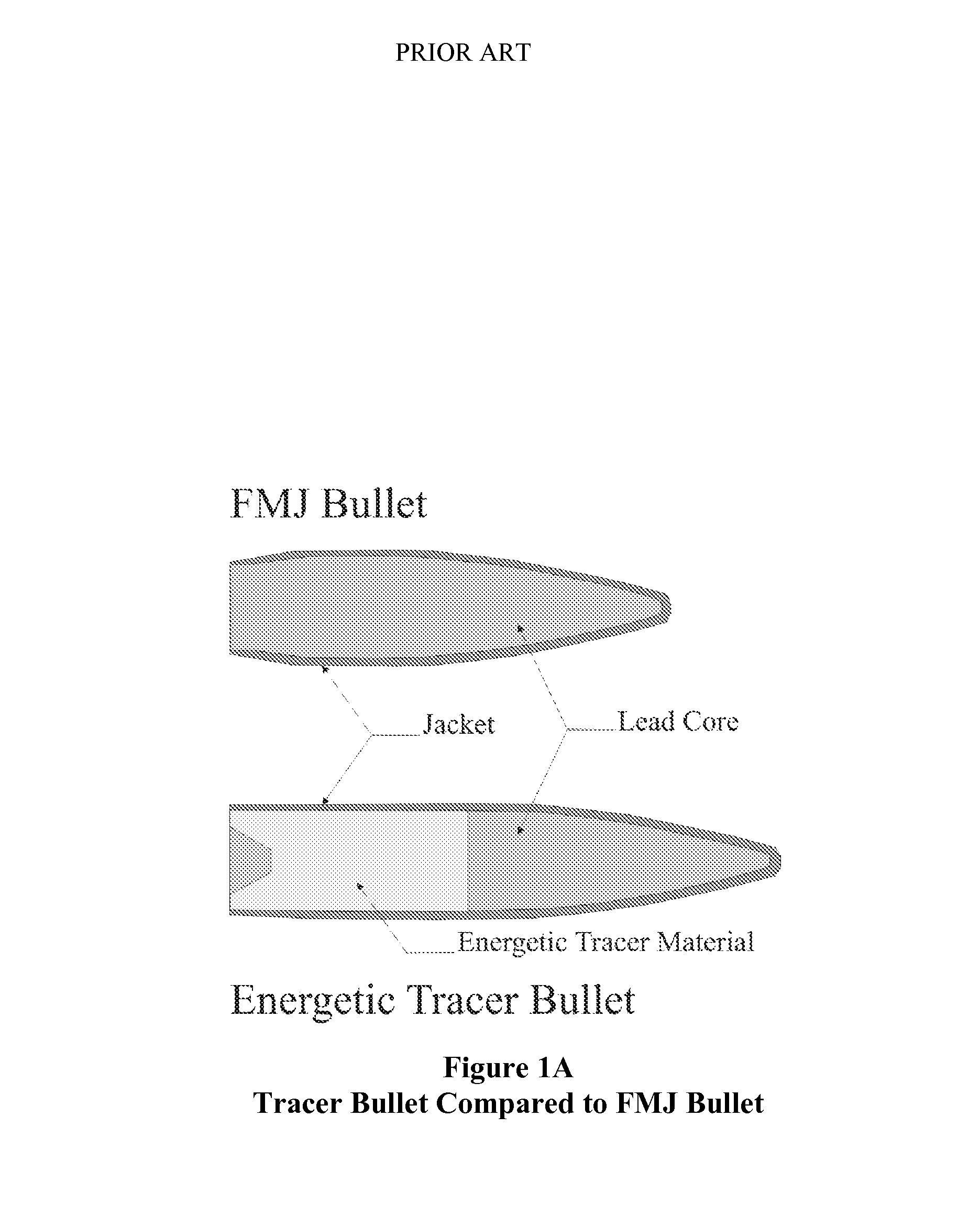
Energetic tracers can never be a totally reliable indicator of a gunner's aim because the energetic tracers have different aerodynamic properties and weights when compared to standard rounds that are being fired with the energetic tracers.
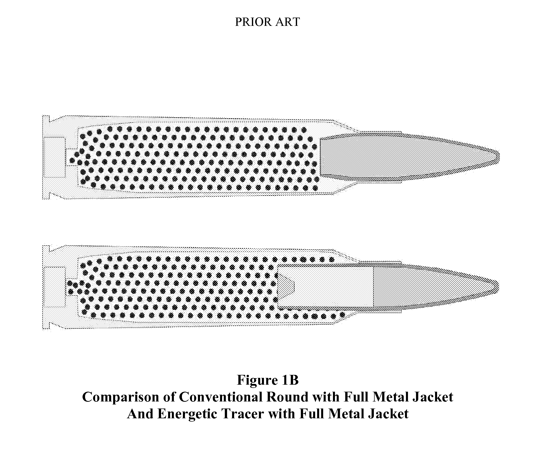
The increased length also adds to the complexity of manufacture because the tracer bullet takes up additional space in the cartridge that would otherwise be used for the propellant in a non-tracer cartridge.
Manufacturing of ammunition has numerous hazards associated with it.
When coupled with energetic tracer manufacturing the problems increase greatly.
Primer material and gunpowder expose manufacturers to some risk of explosion and fire, but these materials are absolutely necessary for the manufacturing of energetic tracer ammunition.
Energetic tracer material increases the hazard to military ammunition manufacture.
Another problem associated with conventional tracers is that they typically leave behind a narrow cloud of burning material that can be up to about a meter long.
While this increases the visibility of the tracer to the shooter, it also makes the tracer visible to the target and unfriendly observers in the surrounding area.
Further, conventional tracers have resulted in fires on training ranges, as well as in the field, where fires are caused by the continued burning of the pyrotechnic material upon impact within the target area.
However, such attempts still result in a tracer bullet with a mass substantially different than the normal bullet.
Such tracer rounds require an added manufacturing expense because of the need to separate the individual chemicals prior to firing.
This separation of chemicals may also take up space in the bullet making it either less massive, or making the bullet longer to provide for the chemical chambers.
The separation of chemicals will also make the bullet more prone to damage during handling.
Furthermore, the chemoluminescent tracers can only be seen in flight by way of a transparent window in the bullet, which has practical constraints due to the material limitations and installation of the window.

Method used


Image

  • Hybrid-luminescent munition projectiles
  • Hybrid-luminescent munition projectiles
  • Hybrid-luminescent munition projectiles

Examples


example 1

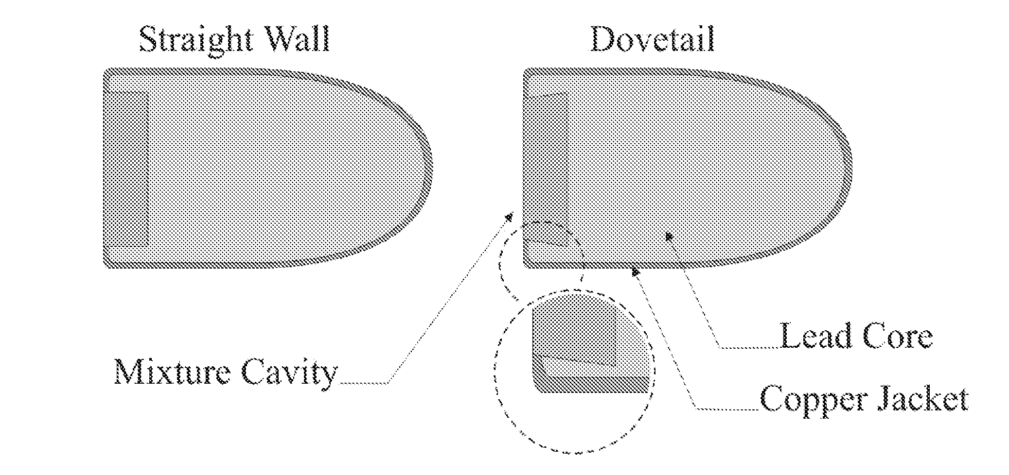
[0054]Various mixtures of luminescent materials and binders, as indicated in Table 1, were prepared and used to coat 5.56 mm projectiles. The rear of each projectile was painted with the various combinations of LM and binder mixtures as shown in Table 1, wherein the ratio of LM:binder was 1:4. The only alteration made to the projectiles was the addition of these painted mixtures. The painted projectiles were then oven cured at a temperature of about 160° C. for at least an hour.

[0055]The projectiles in Table 1 were put through two tests. In the first test each of eight modified 5.56 mm projectiles was fired into a sandbag in daylight at close range to determine the ability of the various LM and binder mixtures to adhere to the projectiles. One projectile fragment was recovered for each of the fired rounds. Results showed that each recovered bullet still contained varying amounts of LM attached to the now-fragmented bullet.

[0056]In the second test the projectiles were fired in a 275 ...

example 2

[0057]Two combinations were chosen for this example. The first combination was NP-2830 luminescent material with the PPMS binder. The second combination was NP-2830 luminescent material with the VHT Flame Proof Coating binder. Both 5.56 mm and 35 caliber Whelen projectiles were used in this example. The 5.56 mm projectiles were unaltered bullets pulled from factory loaded ammunition. LM was mixed with binder at a 1:4 (LM: binder) mass ratio. The only alterations made to the bullets were the addition of the LM and binder mixtures which were applied to the boat tail rear of each projectile. After the mixture was added, the bullets were oven cured at a temperature of about 160° C. for one hour.

[0058]The 35 caliber Whelen bullets were unaltered bullets pulled from factory loaded ammunition. LM was again mixed with binder at a 1:4 (LM: binder) mass ratio. The only alterations made to the bullets were the addition of the paint mixtures which were applied to the cavity at the base of the b...

example 3

[0060]Pneumatic guns were used to test the projectiles in this example. Pneumatic guns use compressed air or carbon dioxide gas to propel the projectile. Because the pneumatic guns did not burn a propellant; the luminescence that occurred could not be attributed to the effect of a burning propellant on the round as it was fired.

[0061]Three different size projectiles were chosen for this experiment. 17.7 cal pellets, 22 cal pellets, and 68 cal pellets. A pellet is a term usually used to define the bullet or projectile launched from a pneumatic gun. The 17.7 cal and 22 cal pellets are made of lead and have a hollow base similar to the design of a badminton shuttlecock. This hollow base was ideal to contain the LM and binder mixture. The 68 cal pellets were designed and manufactured with the intention of launching them from a modified paintball gun. These large slow moving pellets were to allow for a demonstration of the technology in situations where an energetic firearm demonstration...


PUM


Abstract

Novel hybrid luminescent ammunition (HLA) is provided. The HLA projectiles can include photoluminescent or triboluminescent material, or both. The photoluminescent and triboluminescent material can be placed at various locations on the projectile. In one configuration, the triboluminescent material that gives off light when the projectile impacts the target. In another configuration, a photoluminescent material provides a during flight and the triboluminescent material provides identification of target impact. In another configuration, the triboluminescent material is used to provide both the ballistic trace and the impact identification. Methods of making the HLA are also provided.

Description

CROSS REFERENCE TO RELATED APPLICATIONS[0001]This application is a continuation-in-part of U.S. non-provisional application Ser. No. 11 / 499,535 filed on Aug. 4, 2006, which claims the benefit to prior U.S. provisional application Ser. No. 60 / 706,089 filed on Aug. 5, 2005.FIELD OF THE INVENTION[0002]This invention relates to luminescent material used in ammunition projectiles and their methods of manufacture. More particularly, the invention relates to luminescent materials which are photoluminescent or triboluminescent.BACKGROUND OF THE INVENTION[0003]Most modern military forces use energetic tracers based on technology that was developed in the early 1900s. Energetic tracer projectiles generate light through the use of energetic material imbedded in the rear of the projectile, similar to the effect of a burning road flare. Despite various technological advancements that have been made in tracers over the years since their introduction, energetic tracers nevertheless have several sh...

Claims


Application Information

Patent Timeline
Patent Type & Authority Patents(United States)
IPC IPC(8): F42B30/02F42B12/38
CPCF42B12/38F42B12/40
Inventor HOLLERMAN, WILLIAM ANDREWBERGERON, NOAH PAULBROUSSARD, BRADY MARTIN
Owner UNIVERSITY OF LOUISIANA AT LAFAYETTE
Learn More