
Outlet valve for a frost-preventing faucet

a technology of outlet valve and faucet, which is applied in the direction of service pipe system, water supply installation, drawing-off water installation, etc., can solve the problems of inconvenience for users, redundant mist easily leaks out of the interstices of the structure, and leaking problems especially occurring

Active Publication Date: 2013-03-26
WU HUNG NENG
View PDF7 Cites 8 Cited by
  • Summary
  • Abstract
  • Description
  • Claims
  • Application Information

AI Technical Summary

Benefits of technology

The present invention relates to an improved outlet valve for a frost-preventing faucet. The valve has a central bottom with an inlet passage and outlet passage at two sides. The invention includes an elastic element and an axial post for controlling the water flow. A first stop ring is placed around the valve, a second stop ring is placed around the stop sleeve, and a bottom of the second stop ring is placed above a top porcelain disc. The valve compresses the elastic element when water pressure is larger than the elastic element's rebounding force, allowing water to enter the outlet hole and further upward in the faucet. When water pressure is smaller than the elastic element's rebounding force, the valve compresses an axial post of the stop, preventing the porcelain valve unit from freezing and controlling the water flow. The technical effect of this invention is to provide a more efficient and reliable outlet valve for frost-preventing faucets.

Problems solved by technology

Nonetheless, redundant mist easily leaks out of interstices of the structure.
Aforementioned leaking problem is especially occurred in the Frigid Zone or the area that is easily iced up in winter in view of the low temperature.
Obviously, inconvenience for users and wastage of water are resulted.

Method used


Image

  • Outlet valve for a frost-preventing faucet
  • Outlet valve for a frost-preventing faucet
  • Outlet valve for a frost-preventing faucet

Examples


Embodiment Construction

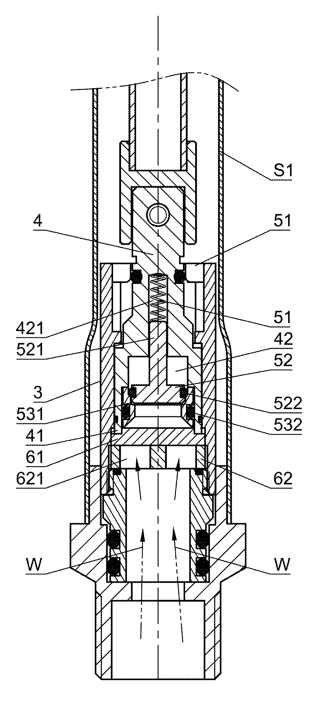
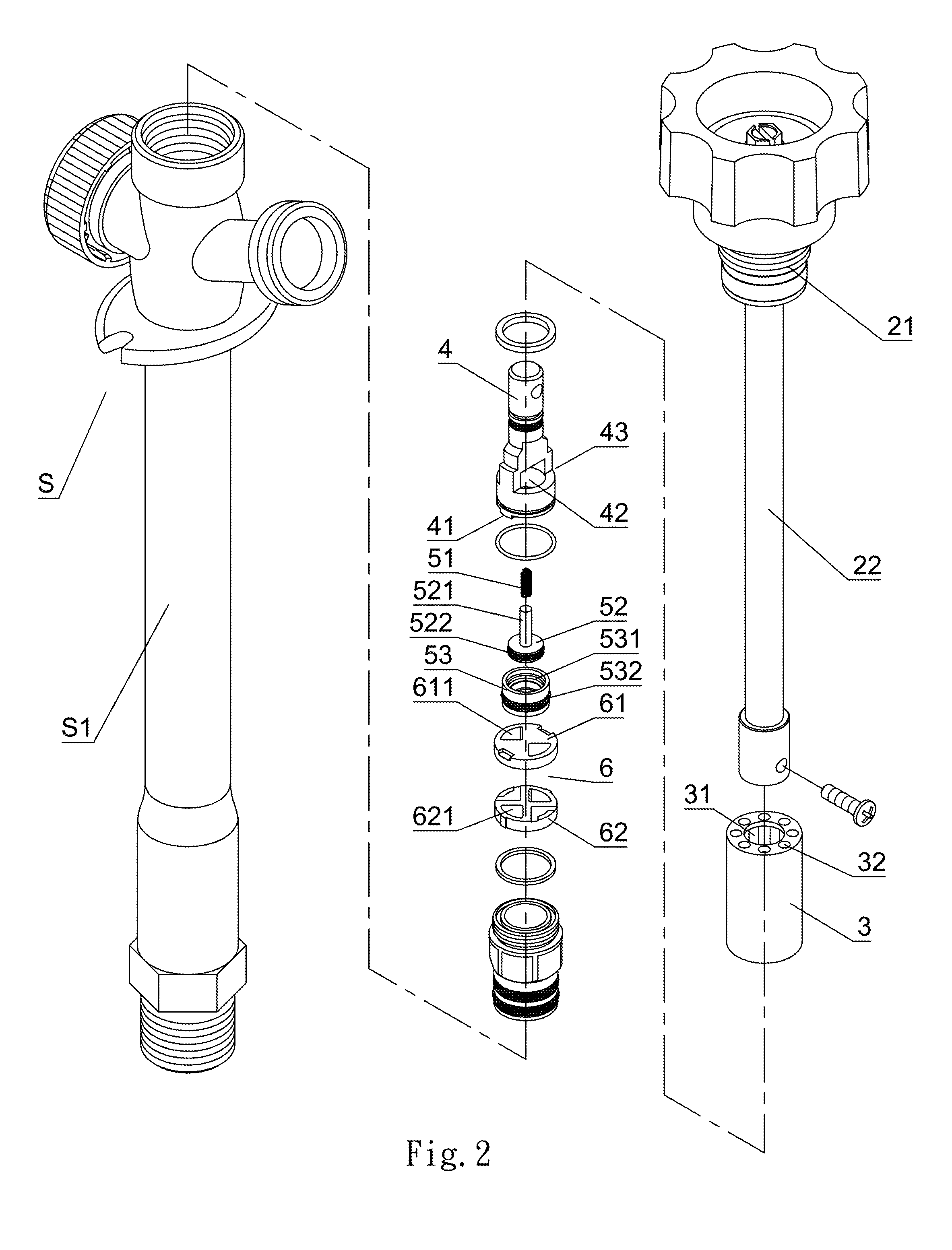
[0013]The present invention is shown by FIGS. 2 and 3 as follows.

[0014]An improved outlet valve for a frost-preventing faucet comprises a tubular receiving valve seat 3 with an open lower end, and a columnar water controlling plug 4 whose bottom end includes a protrudent portion 41. The protrudent portion 41 of the columnar water controlling plug 4 is embedded into two sides of a top face of a butterfly-shaped top porcelain disc 61 disposed under the plug, thereby allowing a turning adjustment of aiming an outlet gate 611 of the top porcelain disc 61 at an outlet gate 621 of a bottom porcelain disc 62. A top end of the columnar water controlling plug 4 is disposed within an axial hole 31 at a central top of the receiving valve seat 3. A central bottom of the water controlling plug 4 defines an inlet passage 42 extended from downward toward upward into a middle section of the plug 4. An outlet passage 43 is laterally communicated at two sides of the inlet passage.

[0015]Wherein, an ax...


PUM


Abstract

An improved outlet valve for a frost-preventing faucet substantially employs an axial slot defined at a central top inside the inlet passage for being inserted by an elastic element and an axial post. A first stop ring is disposed around the stop valve. The first stop ring and the stop valve are inserted into a limiting slot of a hollow stop sleeve disposed under the stop valve. A second stop ring disposed around the stop sleeve is inserted into a lower section of an inner wall of the inlet passage. A bottom of the second stop ring is disposed above a top of the top porcelain. Cooperating the subject improved configuration with the top porcelain allows the water to be supplied upward since outlet gates of the bottom porcelain and the top porcelain stay abreast without a blockage. When a water pressure is larger than a rebounding force of the elastic element, the stop valve upwardly compresses the elastic element. Thereby, the water travels through the inlet passage disposed at the middle section of the plug and enters into an outlet hole at the top end of the tubular receiving valve seat. The water is further upwardly guided into a supplying pipe of the faucet. When the water pressure is smaller than the rebounding force of the elastic element, the elastic element compresses the stop valve. Thereby, an axial post of the stop valve is downwardly inserted into the limiting slot of the stop sleeve for impeding the water flow, so that the porcelain valve unit is prevented from freezing, and the water pressure is capable of controlling a feeding of the water flow.

Description

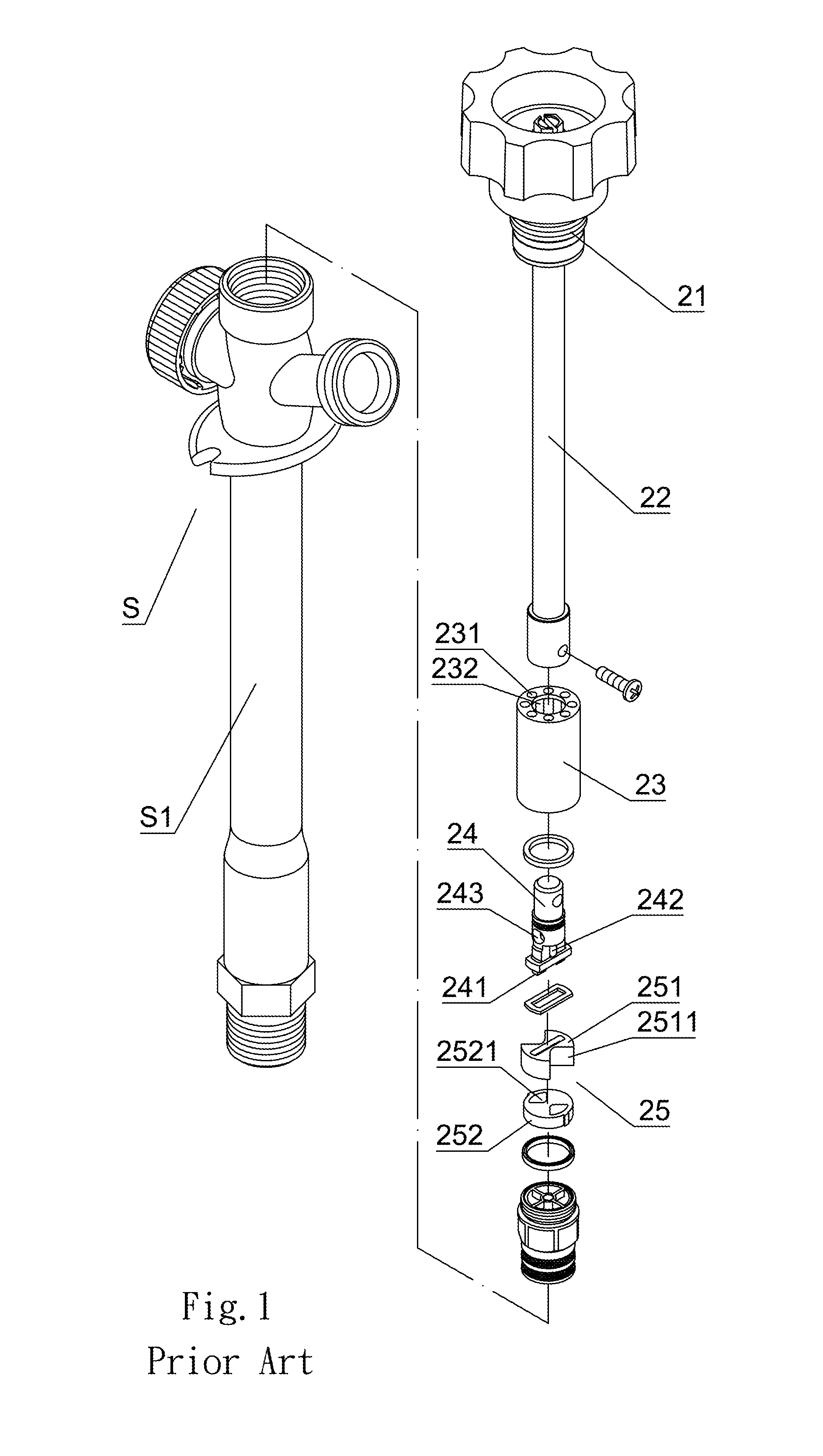
BACKGROUND OF THE INVENTION[0001]1. Field of the Invention[0002]The present invention relates to an improved outlet valve for a frost-preventing faucet that utilizes an elastic element, a stop valve and a stop sleeve disposed between an inlet passage and a porcelain unit defined in a plug to control the flow state of the supplied water along with the water pressure; thereby, the porcelain unit could be prevented from freezing.[0003]2. Description of the Related Art[0004]The existing frost-preventing faucet on the outside ground is mainly installed for users to either draw or sprinkle water conveniently. The conventional frost-preventing faucet S (as shown in FIG. 1) comprises a vertical water supplying pipe S1. A controlling axial seat 21 is mounted on a top portion of the water supplying pipe S1, and a downward connector 22 is connected to a bottom portion of the water supplying pipe S1. Whereby, a top end of a columnar water controlling plug 24 disposed at a bottom end of the conn...

Claims


Application Information

Patent Timeline
Patent Type & Authority Patents(United States)
IPC IPC(8): E03B9/02
CPCE03B7/12E03B9/08Y10T137/1189Y10T137/5497Y10T137/7668Y10T137/88054
Inventor WU, HUNG-NENG
Owner WU HUNG NENG
Learn More