
Card having embedded security element

Active Publication Date: 2013-03-26
GIESECKE & DEVRIENT MOBILE SECURITY GMBH
View PDF13 Cites 1 Cited by
  • Summary
  • Abstract
  • Description
  • Claims
  • Application Information

AI Technical Summary

Benefits of technology

[0016]It is further the object of the present invention to provide such a card, wherein there is guaranteed a good visual recogniz

Problems solved by technology

There are adhesive bonding techniques which make it possible for the security elements to be very durably fixed on the card surface, so that a non-destructive detaching of an adhesively bonded security element is nearly impossible.
Security elements adhesively bonded to an outer surface of a card, however, upon the use of the card, are subject to heavy wear, and in particular in the case of frequently used cards or cards which are used for a very long time, such as ID cards, the relief structures suffer within a too short period of time due to abrasion and other mechanical loads in such a way that the optical effects are lost.
However, a security element to be embedded between card layers is exposed to the effects of heat and pressure during the lamination process of the card layers, and the quality of the relief structures is impaired thereby so much that the optical effects can no longer serve as a security mark.
Through the more careful treatment of the security element areas during the lamination, however, there is achieved only a slight improvement in terms of maintaining the quality of the relief structure, and this improvement is bought at the cost of a worse foil composite in the card areas treated more carefully, which has a negative effect on the visual recognizability of the security features of the security element, and, moreover, in the course of time can lead to a splitting of the card layers in this area.
However, special problems arise in the case of security elements which have relief structures with first and second picture elements, the first picture elements producing to the viewer first, so-called “open” picture information (representation) and the second picture elements producing to the viewer, using a suitable aid, second, so-called “hidden” picture information (representation).
Security elements with relief structures, in particular diffraction structures, with open and hidden picture information

Method used


Image

  • Card having embedded security element
  • Card having embedded security element
  • Card having embedded security element

Examples


Example

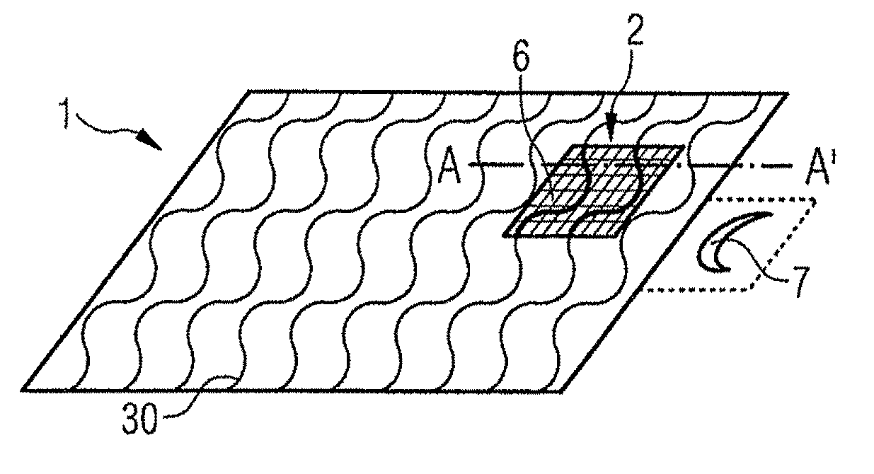
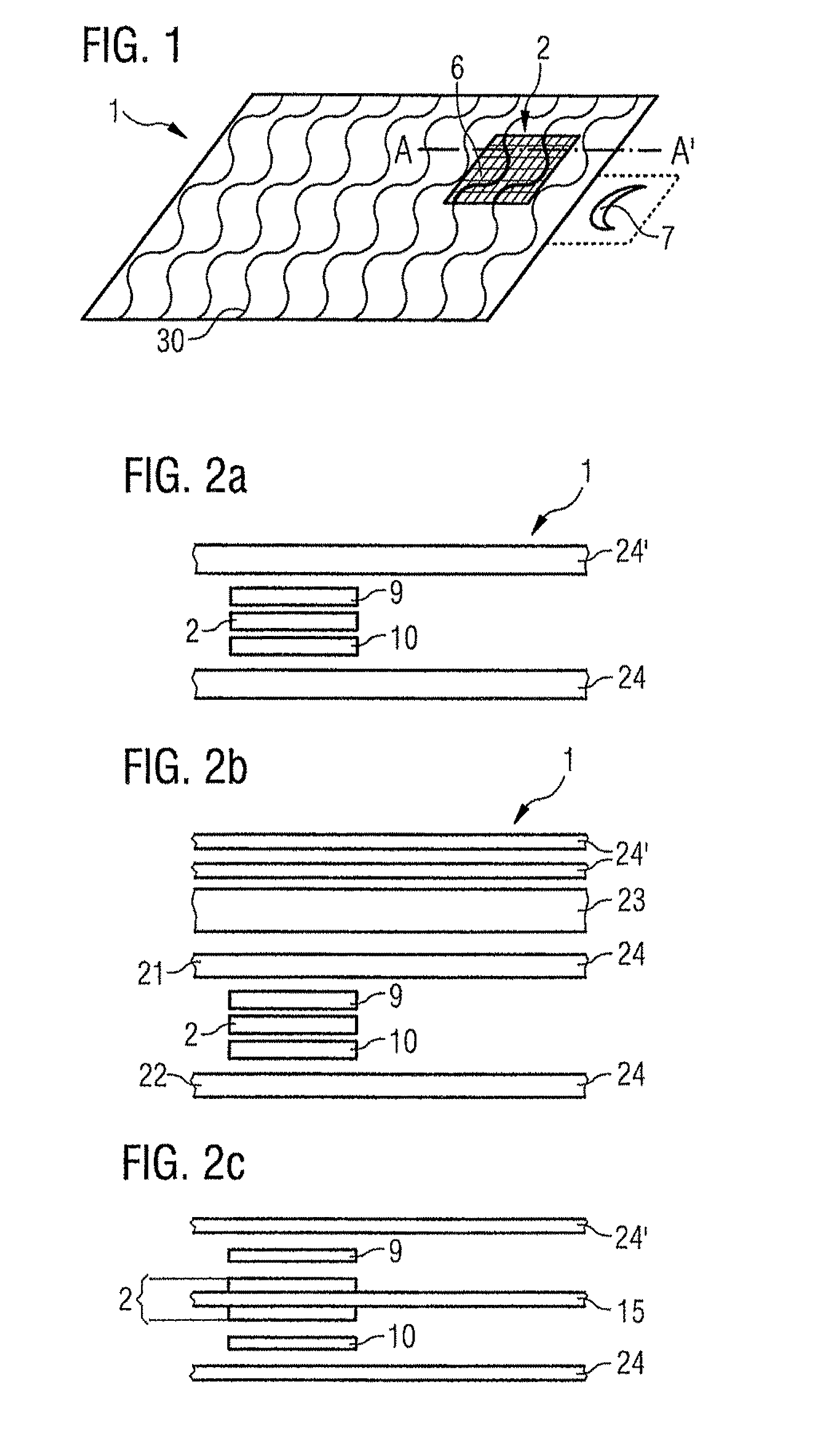
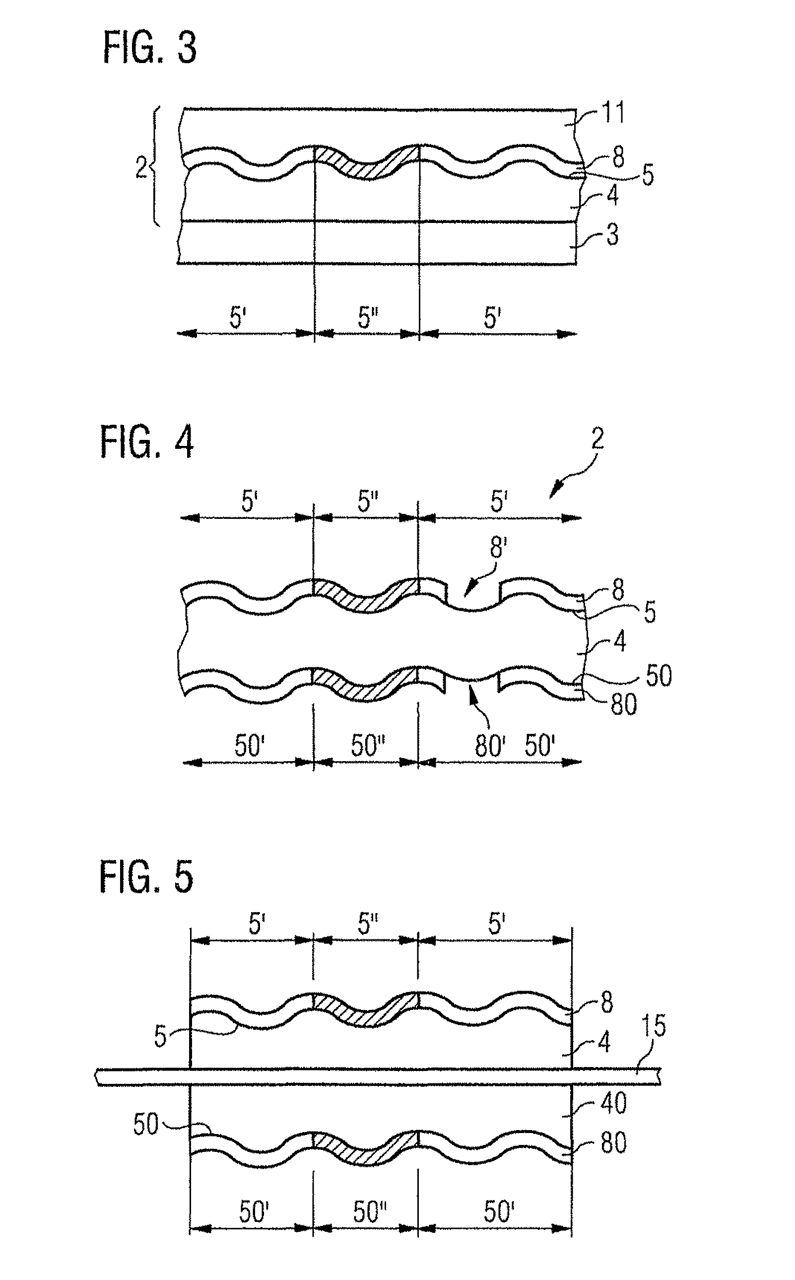
[0064]FIG. 1 shows a card according to the invention in top view. The card 1 has an embedded security element 2. The security element 2 has a diffraction structure, which produces a representation 6 visually recognizable under ambient conditions, in particular when exposed to light in the visible wavelength range, here a diamond pattern, as well as a representation 7 not visually recognizable under ambient conditions, here a moon. The representation 7 is indicated in FIG. 1 as a virtual picture, the representation 7 normally also being projected, using a suitable light source, e.g. a laser with laser light in the red wavelength range, onto a suitably formed ground glass screen. In addition, the card 1 shows a design print 30 which extends in the form of a wave pattern over the entire card surface including the security element 2. The design print 30 is printed, not recognizable in FIG. 1, on the in the card structure inner surface of the card's cover layer covering the security elem...


PUM


Abstract

The invention relates to a card (1), such as a credit card or ID card, which has several layers laminated with each other, wherein between a first card layer (21) and a second card layer (22) there is embedded a security element (2) which has a plastic or lacquer layer (4) with a relief structure (5). The relief structure has areas (5′, 5″) with different picture elements and produces a visible representation (6) and a hidden representation (7) which can be made visible with aids. The security element is adhesively bonded by adhesive layers (9, 10) to the two card layers (21, 22) between which it is embedded, the adhesives being chosen from the group which consists of physically drying adhesives and adhesives crosslinkable by heat, preferably water-based. Upon use of an adhesive crosslinkable by heat, the crosslinking temperature of the adhesive is lower than the softening temperature of the plastic or the lacquer layer (4) in which there is present the relief structure (5). The invention also relates to a method for manufacturing such a card.

Description

BACKGROUND OF THE INVENTION[0001]1. Field of the Invention[0002]The invention relates to a multilayer card, in particular credit card, bank card or ID card such as national ID document, driver's license or other identification document, which has a security element with relief structures which produce open and hidden representations, as well as a method for manufacturing the card.[0003]2. Related Art[0004]Cards which for different kinds of reasons represent an object of value, such as bank cards, credit cards or ID cards, must be protected against forgery. For securing such value cards against forgery, there are often employed security elements with security features in the form of relief structures, for example embossed holograms, the manufacturing of which requires a significant technological effort. One reason for the popularity of such security elements is that the optical effects yielded through the diffraction structures or refractive structures cannot be reproduced even by st...

Claims


Application Information

Patent Timeline
IPC IPC(8): G06K19/02B42D15/00
CPCB32B37/1207B32B37/185G06K19/08B42D25/328B32B2305/347B32B2425/00Y10T156/1039B42D25/455B42D25/47B42D2033/30G07F7/0813B42D25/00B42D25/23B42D25/324B42D25/373
Inventor ENDRES, GUNTEROWEGER, BERNDSTAHL, JURGEN KARLSALZER, TOBIAS
Owner GIESECKE & DEVRIENT MOBILE SECURITY GMBH
Learn More