
Novel vision system for photoetching equipment

A vision system and lithography equipment technology, applied in the field of new vision systems, can solve problems such as the failure to select the spectral characteristics, shape and background of the observed objects, and the poor use effect of the vision system, so as to achieve good observation and recognition of objects. , Improve the effect of alignment accuracy

Active Publication Date: 2012-10-10
ZHONGSHAN AISCENT TECH
View PDF5 Cites 6 Cited by
  • Summary
  • Abstract
  • Description
  • Claims
  • Application Information

AI Technical Summary

Problems solved by technology

[0004] However, the existing visual system does not work well, and the angle, spectrum and color temperature of the illumination light, and the selection of the spectral characteristics, shape and background of the observed object are not up to the requirements.

Method used


Image

  • Novel vision system for photoetching equipment
  • Novel vision system for photoetching equipment
  • Novel vision system for photoetching equipment

Examples


Embodiment Construction

[0022] The present invention is described in detail below in conjunction with accompanying drawing:

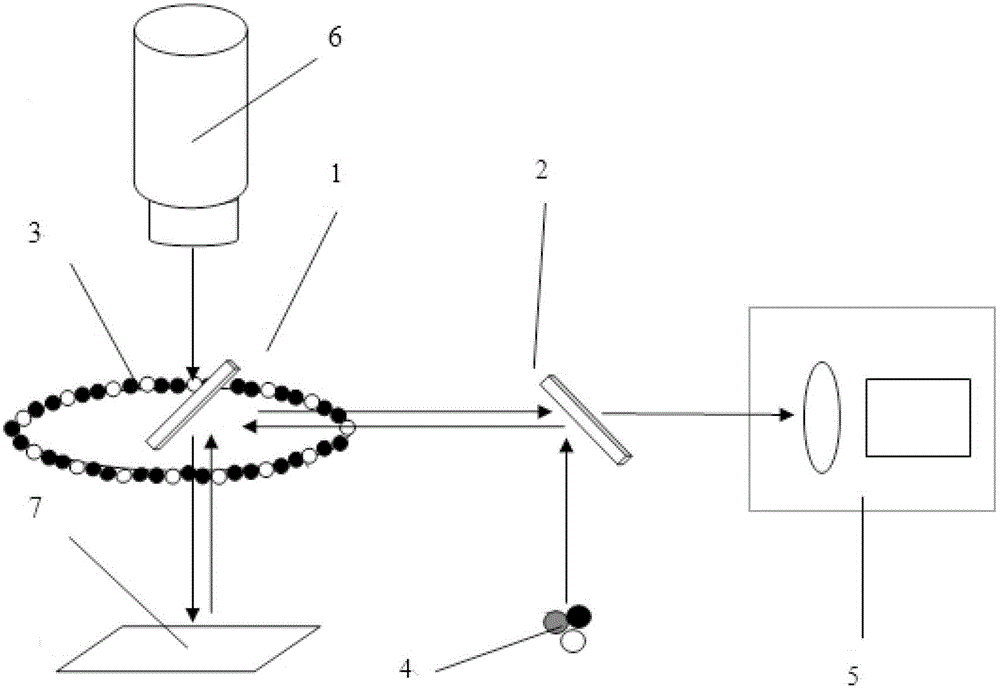
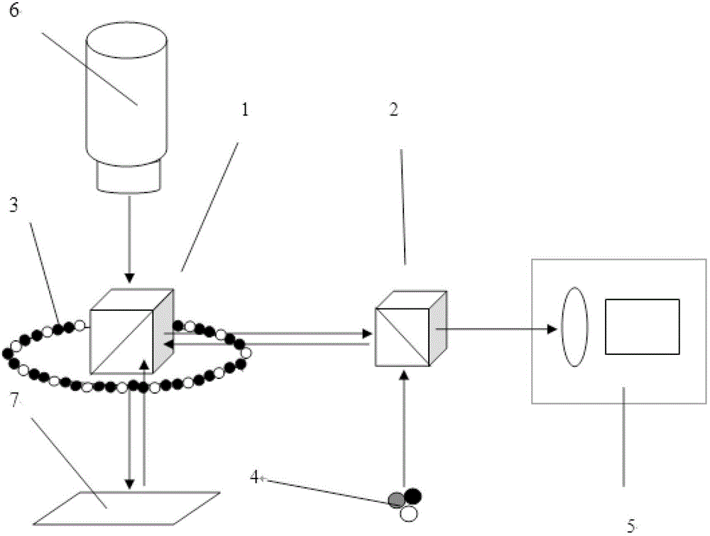
[0023] As shown in the figure, a new type of vision system for lithography equipment includes R, G, B three-color LED light sources and light sensors. In addition, it is also equipped to refract R, G, B three-color LED light sources to the light sensor. spectroscope.

[0024] Specifically, the beam splitter is one or more beam splitting prisms or beam splitting mirrors. The R, G, B three-color LED light sources are single or multiple sets of R, G, B three-color LED light sources. The three-color light emitted by the R, G, and B three-color LED light sources is reflected by the object, refracted by the beam splitter, and then reaches the light sensor to form a visible image. When there is one beam splitter, the R, G, and B three-color LED light sources are a single group of three-color LED light sources. When there are multiple beam splitters, the number of groups of the R, ...


PUM

PropertyMeasurementUnit
wavelengthaaaaaaaaaa

Abstract

The invention relates to a novel vision system for photoetching equipment, which comprises R (Red), G (Green) and B (Blue) LED (Light-Emitting Diode) light sources and an optical sensor and is also provided with spectroscopes for refracting the R, G and B LED light sources onto the optical sensor. The spectroscopes are one or a plurality of beam splitter prisms or beam splitting reflectors; one group or a plurality of groups of R, G and B LED light sources are provided; and light with three colors, which is emitted by the R, G and B LED light sources, is reflected by an object, and then is refracted by the spectroscopes to the optical sensor, so as to form a visual image. The invention provides the novel vision system which has the optimal comparison and detection effects of selecting the angle, a spectrum and the color temperature of the illuminating light and the spectral characteristic, the shape and the background of the observed object and can further observe and identify the object and improve the alignment accuracy of a substrate.

Description

【Technical field】 [0001] The present invention relates to a new vision system for lithographic equipment. 【Background technique】 [0002] Laser lithography equipment used in large-scale integrated circuits and FPD / TFT / OLED / TP large-screen display industries. It consists of laser light source, spatial light modulator (SLM), optical system, vision system, mobile platform, control circuit, data conversion software and server data processing and transmission system. [0003] Among them, the vision system plays an important role in the alignment of the substrate, observation and debugging, and inspection and testing. [0004] However, the existing visual system is not effective, and the angle, spectrum and color temperature of the illumination light, and the spectral characteristics, shape and background selection of the observed object cannot meet the requirements. 【Content of invention】 [0005] The purpose of the present invention is to overcome the deficiencies in the pri...

Claims


Application Information

Patent Timeline
Patent Type & Authority Applications(China)
IPC IPC(8): G03F7/20G02B27/10
Inventor 梅文辉杜卫冲曲鲁杰
Owner ZHONGSHAN AISCENT TECH
Learn More