Electric power generating apparatus
a technology of electric power generation and electric power, which is applied in the direction of control/drive circuits, dynamo-electric machines, structural associations, etc., can solve the problems of affecting the reciprocal operation affecting the electrical performance of the permanent magnet, and leaking outside the case, so as to achieve stable operation of generating electric power.
- Summary
- Abstract
- Description
- Claims
- Application Information
AI Technical Summary
Benefits of technology
Problems solved by technology
Method used
Image
Examples
first embodiment
[0029]Embodiments of the present invention will be described with reference to the drawings.
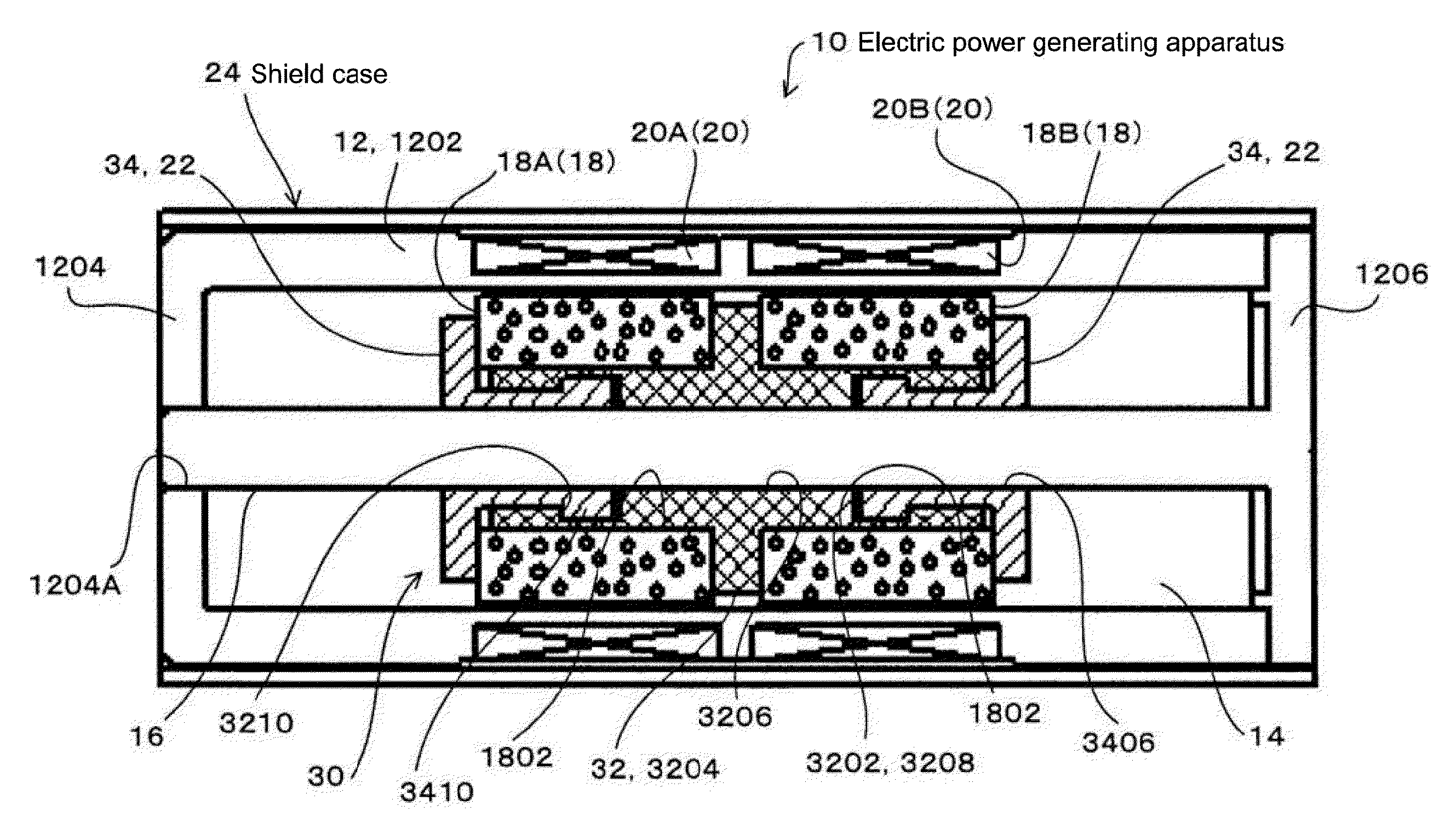
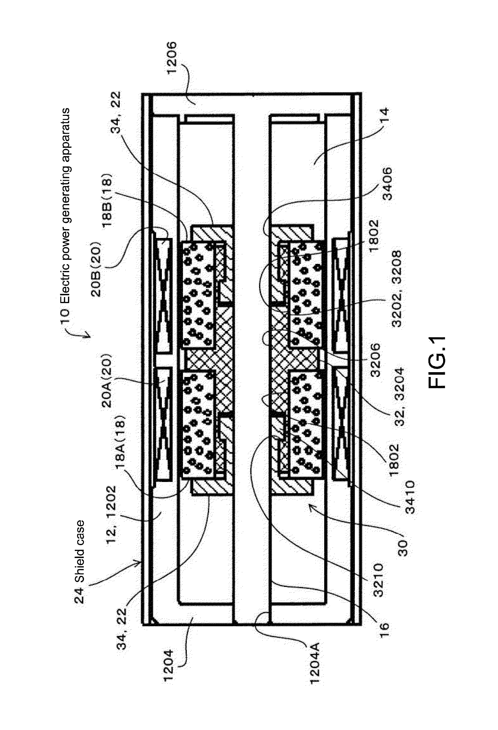
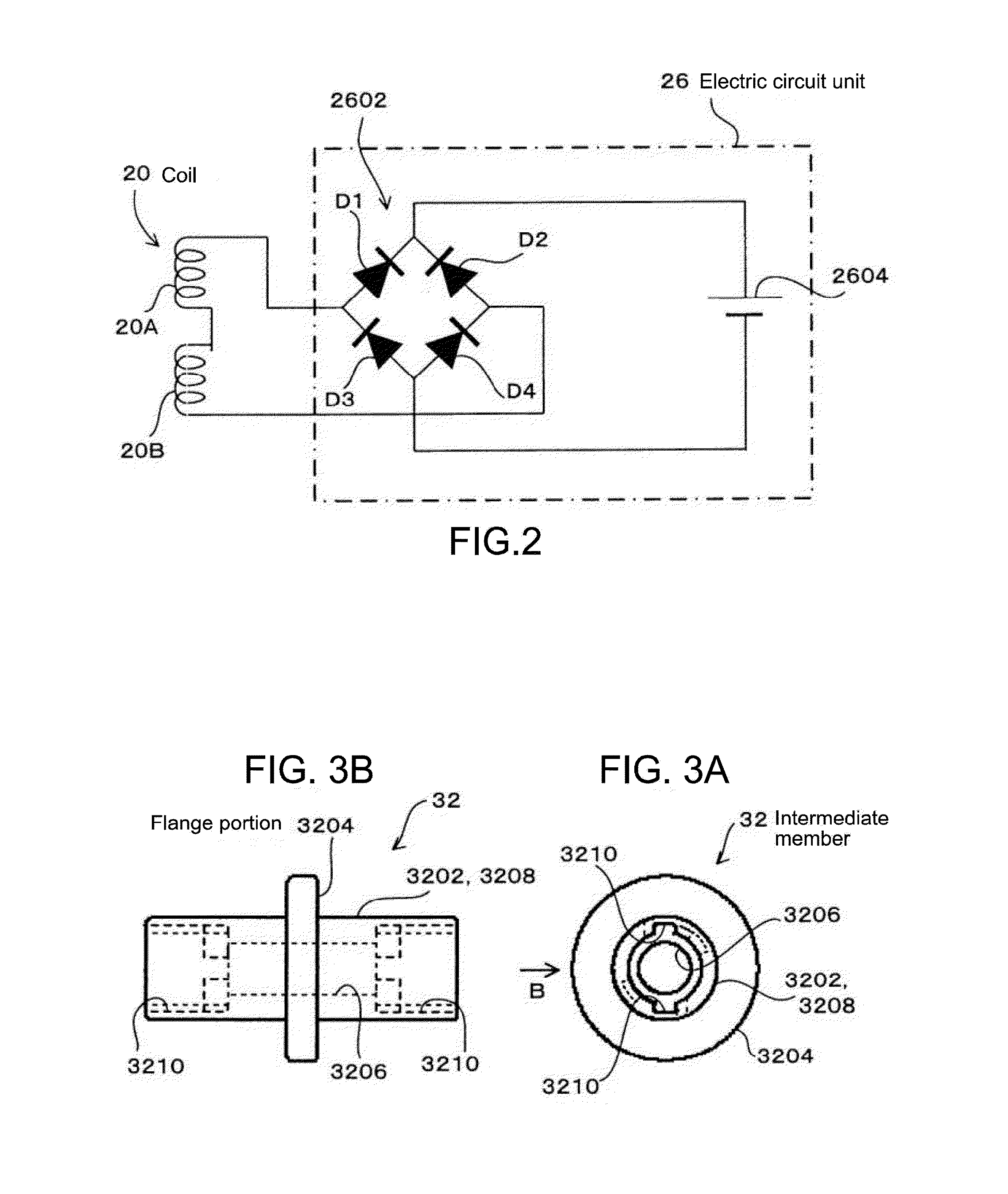
[0030]FIG. 1 is a cross-sectional view showing a structure of an electric power generating apparatus 10 according to this embodiment. FIG. 2 is a circuit diagram of an electric circuit unit 26. FIG. 3A is a front view of an intermediate member 32, and FIG. 3B is a side view of the intermediate member 32 viewed from a side thereof in a direction of the arrow B of FIG. 3A. FIG. 4A is a front view of a cap member 34, and FIG. 4B is a cross-sectional view of the cap member 34 taken along the line B-B of FIG. 4A.
[0031]The electric power generating apparatus 10 includes a casing 12, a space portion (interior space) 14, a guide shaft 16, a permanent magnet 18, a coil 20, a buffer member 22, and a shield case 24 that are shown in FIG. 1, and further includes the electric circuit unit 26 shown in FIG. 2.
[0032]The casing 12 is made of a nonmagnetic, nonconductive material. In this embodiment, the casin...
second embodiment
[0111]Next, a description will be given on a second embodiment.
[0112]The second embodiment is different from the first embodiment in that the shield case 40 covers an entire area of two end surfaces disposed at the both ends in the longitudinal direction, in addition to the entire area of the circumferential surface of the outer surface of the casing 12, that is, the shield case 40 covers the entire surface of the casing 12.
[0113]FIG. 5 is a cross-sectional view of the electric power generating apparatus 10 according to the second embodiment, and FIG. 6 is an operation explanatory diagram of the electric power generating apparatus 10 according to the second embodiment.
[0114]It should be noted that in the second embodiment and subsequent ones, components that are similar to or the same as those of the first embodiment are denoted by the same reference numerals or symbols, and their descriptions will be omitted.
[0115]As shown in FIG. 5, the shield case 40 includes first, second, and t...
third embodiment
[0127]Next, a description will be given on a third embodiment.
[0128]In the third embodiment, the outline of the electric power generating apparatus 10 is set to be the same as the outline of a casing of a commercially available primary battery or secondary battery.
[0129]FIGS. 7 and 8 are cross-sectional views of the electric power generating apparatus 10 according to the third embodiment.
[0130]As shown in FIG. 7, as in the first embodiment, the electric power generating apparatus 10 includes the casing 12, the space portion 14, the guide shaft 16, the permanent magnet 18, the coil 20, the buffer member 22, a shield case 50, and the electric circuit unit 26.
[0131]The electric power generating apparatus 10 has the same shape as the outline of the commercially available primary battery or secondary battery.
[0132]A positive-electrode terminal portion 52 and a negative-electrode terminal portion 54 are provided in the same shape at the same position as a positive-electrode terminal porti...
PUM
 Abstract
Description
Claims
Application Information
 - R&D
- Intellectual Property
- Life Sciences
- Materials
- Tech Scout
- Unparalleled Data Quality
- Higher Quality Content
- 60% Fewer Hallucinations
Browse by: Latest US Patents, China's latest patents, Technical Efficacy Thesaurus, Application Domain, Technology Topic, Popular Technical Reports.
© 2025 PatSnap. All rights reserved.Legal|Privacy policy|Modern Slavery Act Transparency Statement|Sitemap|About US| Contact US: help@patsnap.com


