Production method of vibrating motor and rotor for vibrating motor

a technology of vibrating motor and rotor, which is applied in the manufacture of stator/rotor bodies, mechanical energy handling, and applying solid insulation, etc., can solve the problems of limited coaxial accuracy of rotors, the number of parts is not easily reduced, and the production cost of rotors is not reduced. , the effect of reducing the number of parts

Active Publication Date: 2013-03-26
MINEBEAMITSUMI INC
View PDF5 Cites 5 Cited by
  • Summary
  • Abstract
  • Description
  • Claims
  • Application Information

AI Technical Summary

Benefits of technology

[0007]In the production method in which the rotor, including inserting an annular diamagnetic material and a permanent magnetic material into a mold, injecting resins such as thermoplastics into the mold and integrally forming the resins, the annular diamagnetic material and a permanent magnet, the number of parts is not easily reduced. In the method in which a shaft is fixed to an eccentric weight by adhesives, since a clearance for adhesives is necessary, accuracy such as coaxial accuracy of a rotor is limited. According to conventional production methods, a rotor for a vibrating motor requires many steps for production, and production costs for the rotor are not reduced. Therefore, an object of a present invention is to provide a rotor having high coaxial accuracy for a vibrating motor, which can be obtained by simplified processes.

Problems solved by technology

In the production method in which the rotor, including inserting an annular diamagnetic material and a permanent magnetic material into a mold, injecting resins such as thermoplastics into the mold and integrally forming the resins, the annular diamagnetic material and a permanent magnet, the number of parts is not easily reduced.
In the method in which a shaft is fixed to an eccentric weight by adhesives, since a clearance for adhesives is necessary, accuracy such as coaxial accuracy of a rotor is limited.

Method used


Image

  • Production method of vibrating motor and rotor for vibrating motor
  • Production method of vibrating motor and rotor for vibrating motor
  • Production method of vibrating motor and rotor for vibrating motor

Examples


second embodiment

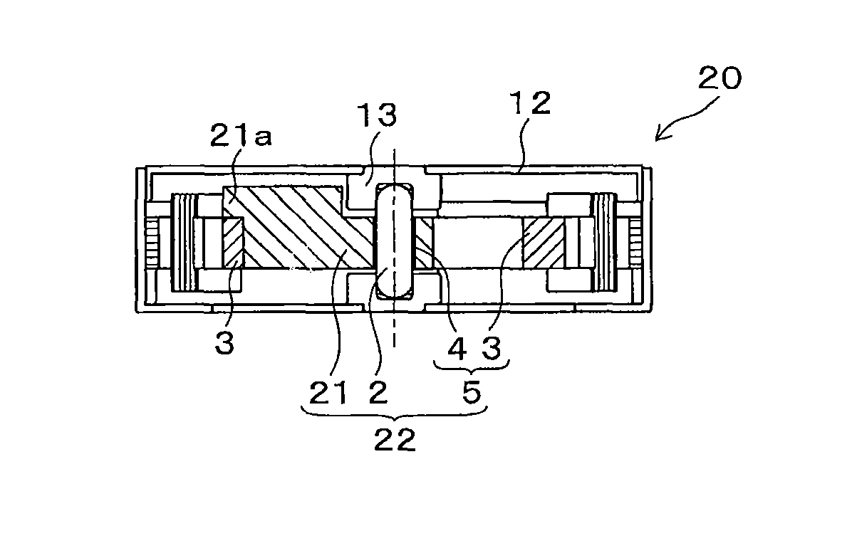
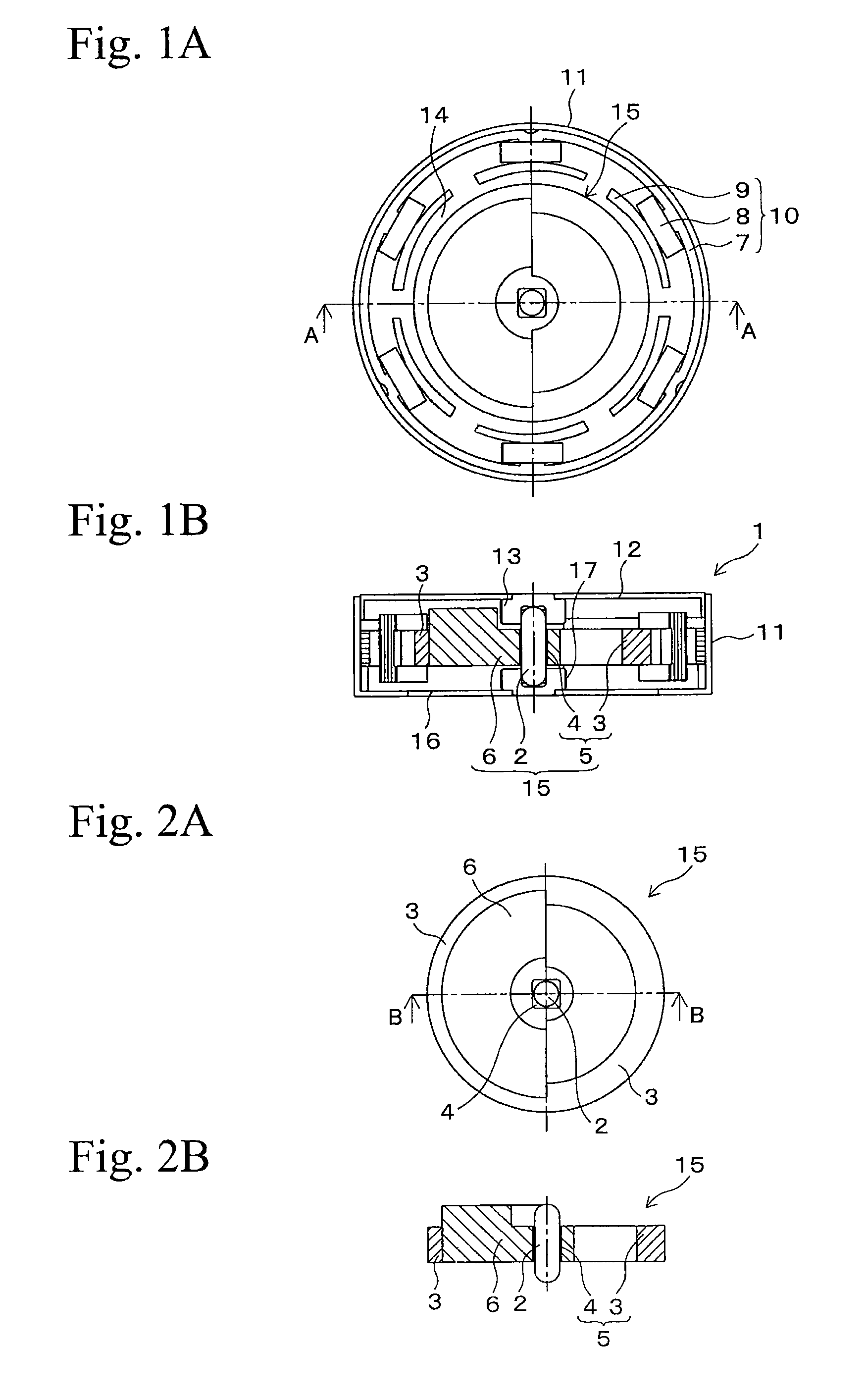
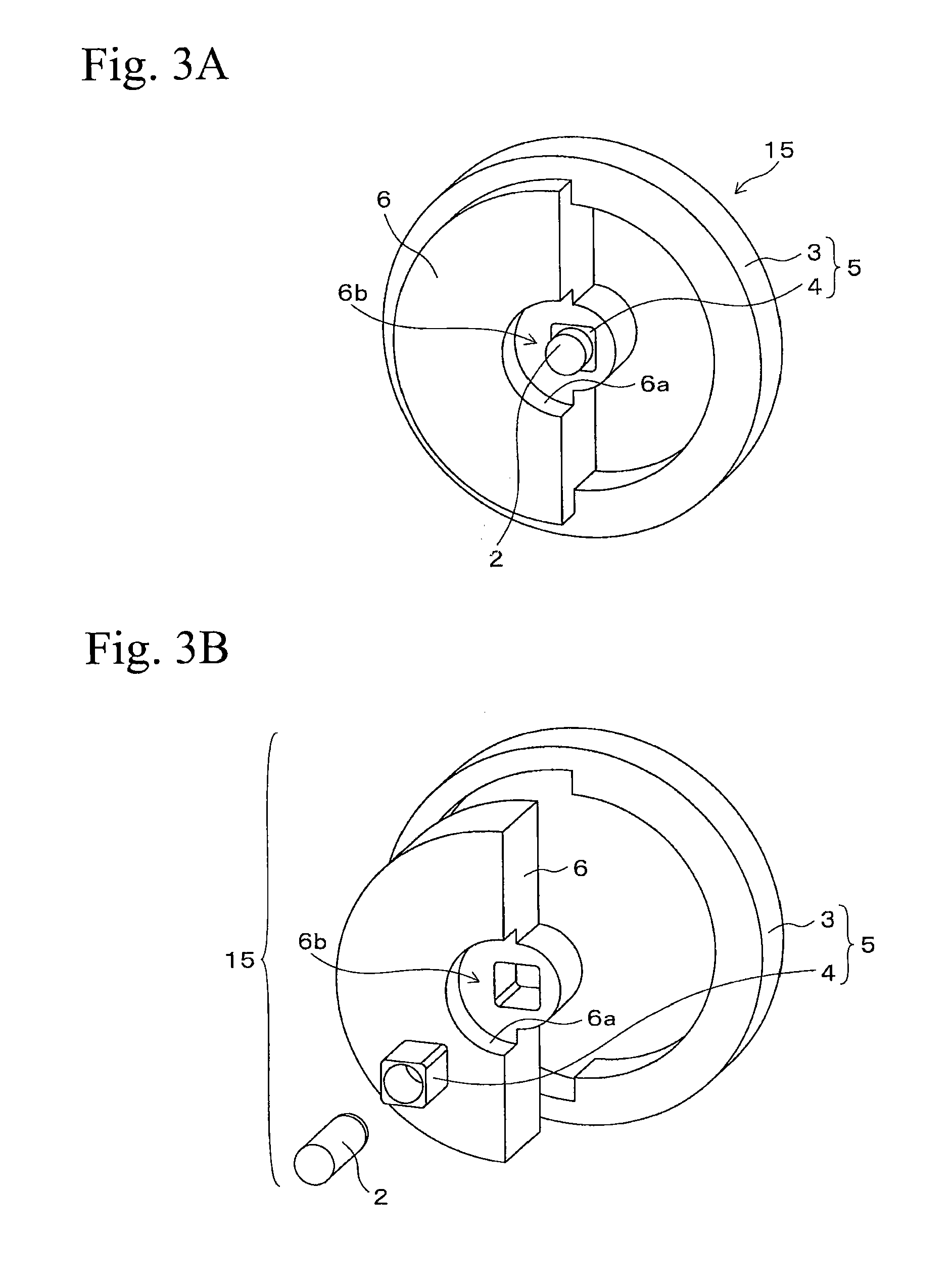
[0062]FIG. 4 A is a plane view and FIG. 4B is a cross sectional view of a vibrating motor 20 in accordance with a second embodiment, each of FIGS. 4A and 4B is viewed from the same direction as FIGS. 1A and 1B. The shape of an eccentric weight 21 of a rotor 22 is different from that of the vibrating motor 1 in FIGS. 1A and 1B. In the vibrating motor 20, an extensional portion 21a is provided, in which the outer surface of the eccentric weight 21 is extended up to the outer surface of the permanent magnet 3 for more effective vibration. The shape of the extensional portion 21a partially overlaps with the permanent magnet 3 when viewed from an axial direction. According to the structure of the embodiment, a mass of the extensional portion 21a is added to an outer surface of the rotor 22, whereby mass unbalance to the shaft 2 is increased and more effective vibration is obtained.

[0063]FIG. 5A is a plane view of the rotor 22 and FIG. 5B is a cross sectional view of the rotor 22 taken al...

third embodiment

[0065] FIG. 6A is a plane view and FIG. 6B is a cross sectional view of a vibrating motor 30, each of FIGS. 6A and 6B is viewed from the same direction as FIGS. 1A and 1B. FIG. 7A is a plane view of a rotor 32 in FIG. 6A, and FIG. 7B is a cross sectional view of the rotor 32 taken along line B-B in FIG. 7A. The vibrating motor 30 is shown in FIGS. 6A and 6B. In the vibrating motor 30, an extensional portion 31a is provided, and in order to obtain effective vibration, one side of an outer surface of the eccentric weight 31 is radially extended up to the position overlapping with the pole teeth 9 when viewed from an axial direction. The extensional portion 31a does not contact the members in the stator 10. Portions other than the eccentric weight 31 in the vibrating motor 30 are the same as the portions of the vibrating motor 1 shown in FIG. 1A. According to the structure, the mass of the extensional portion 31a is added at an outer side of the rotor 32, whereby mass unbalance to the ...

fifth embodiment

[0067] FIG. 10A is a plane view and FIG. 10B is a cross sectional view of a vibrating motor 40, and each of FIGS. 10A and 10B is viewed from the same direction as FIGS. 1A and 1B. FIG. 11A is a plane view of a rotor 52 in FIG. 10A, and FIG. 11B is a cross sectional view of the rotor 42 taken along line B-B in FIG. 11A. A vibrating motor 50 is shown in FIGS. 10A and 10B. In the vibrating motor 50, both axial sides of the outer surface of an eccentric weight 51 are radially extended up to the same position in the vibrating motor 40 shown in FIGS. 8A and 8B. That is, in the vibrating motor 50, an eccentric weight 51 is provided such that both upper and lower axial sides thereof are radially extended as shown in FIG. 10B. An external portion 51a and an external portion 51b are provided at an upper side of the extended portion of the eccentric weight 51, an external portion 51c and an external portion 51d are provided at a lower side of the extended portion. The external portions 51a and...


PUM

PropertyMeasurementUnit
specific gravityaaaaaaaaaa
circumferenceaaaaaaaaaa
axial lengthaaaaaaaaaa

Abstract

A vibrating motor has a shaft, a stator including a yoke having pole teeth extending toward an axis of the shaft from an inner circumference and coils wound around the pole teeth, a rotor including an eccentric weight formed on a radially outer surface of the shaft, and a permanent magnet integrally formed with the eccentric weight, and a bearing device rotatably supporting the rotor maintaining clearance between the inner circumference of the pole teeth and the rotor. The rotor has a structure in which the shaft, the eccentric weight, and the permanent magnet are integrally formed with each other by a thermoplastic magnetic material composing the permanent magnet.

Description

RELATED APPLICATIONS[0001]This application claims priority under 35 U.S.C. §119 to Japanese Patent Application Nos. 2010-012945 filed on Jan. 25, 2010 and 2010-167930 filed on Jul. 27, 2010, the entire contents of which are hereby incorporated by reference.BACKGROUND OF THE INVENTION[0002]1. Field of the Invention[0003]The present invention relates to a production method for a vibrating motor and a rotor for a vibrating motor having a specific structure for fixing an eccentric weight.[0004]2. Related Art[0005]Some kinds of inner rotor type vibrating motors having a permanent magnet are used in products such as portable telephones. For example, Japanese patent application, First Publication No. 2008-271719 discloses a structure of a vibrating motor having a rotor composed of an axially eccentric weight and a permanent magnet. The vibrating motor includes a stator radially outwardly separated from the rotor for generating power for rotation and having a driving coil and a yoke.[0006]J...

Claims


Application Information

Patent Timeline
Patent Type & Authority Patents(United States)
IPC IPC(8): H02K7/06
CPCH02K1/2733H02K7/063Y10T29/49012Y10T29/49009
Inventor NAKAMURA, MANABUSUZUKI, YUZURUFURUSAKI, HIROYUKI
Owner MINEBEAMITSUMI INC
Why Eureka
Try Eureka