Independent suspension type front drive rear axle assembly

An independent suspension and front drive technology, applied in the direction of brakes, brake components, axles, etc., can solve the problems affecting the overall layout, long drive shaft, increase the weight of the car, etc., to reduce the weight of the rear axle and the weight of the whole vehicle, system system Improved, stable and reliable performance

Inactive Publication Date: 2016-12-07
通天汽车桥(天津)有限公司
View PDF8 Cites 3 Cited by
  • Summary
  • Abstract
  • Description
  • Claims
  • Application Information

AI Technical Summary

Problems solved by technology

[0004] 1. The front rear drive needs to install a transmission shaft between the engine and the rear axle to transmit power. The installation of the transmission shaft not only increases the weight of the vehicle and affects the overall layout, but more importantly, it has a great impact on the battery box layout of the new energy electric bus. great difficulty;
[0005] 2. The front and rear drive require a larger and longer transmission shaft, which will increase the weight of the vehicle and be detrimental to the speed and cruising range of the electric bus;
[0006] 3. The front and rear drive will cause the floor of the vehicle to rise, which in turn will increase the center of gravity of the car and affect the stability of the car.
The crossbeam of the rear axle of the car supports the chassis of the car through the leaf spring suspension. As a result, the height of the car chassis from the ground is higher, resulting in a higher center of gravity of the car and a decrease in the driving stability of the car. The higher car chassis is especially inconvenient for large and medium-sized electric buses. The layout of battery packs greatly restricts the battery life of large and medium-sized electric buses

Method used


Image

  • Independent suspension type front drive rear axle assembly
  • Independent suspension type front drive rear axle assembly
  • Independent suspension type front drive rear axle assembly

Examples


Embodiment Construction

[0026] Further illustrate the present invention below in conjunction with embodiment and accompanying drawing.

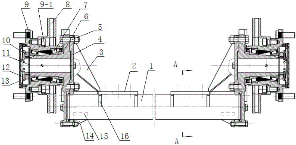
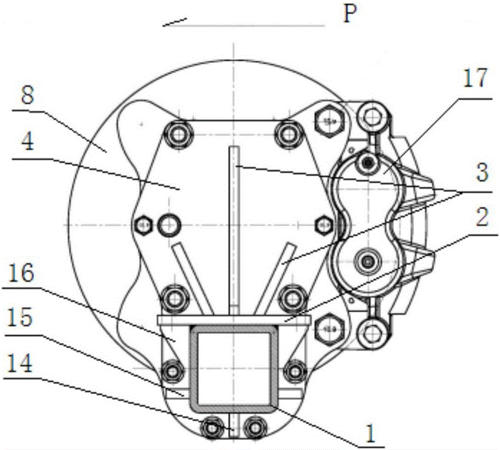
[0027] Such as figure 1 , 2 In the shown embodiment, the two ends of the rear axle beam 1 are provided with symmetrical flanges 4 that are fitted and fixed by welding, and the upper surfaces of the two ends of the rear axle beam 1 are provided with flanges that are welded and fixed to the rear side of the rear axle beam and the flange. The mounting seat plate 2 of the leaf spring suspension (not shown) is provided with a welded and fixed reinforcing rib plate I3 between the mounting seat plate 2 and the rear side of the flange plate 4 .

[0028] The top of each flange 4 is symmetrically provided with a rear axle head 6 fastened by symmetrically arranged bolts 5, and the center distance between the center of the rear axle head 6 and the rear axle beam 1 is 130-160mm, and the center distance of the embodiment is 150mm.

[0029] The rear axle head 6 supports the rear...


PUM


Abstract

The invention discloses an independent suspension type front drive rear axle assembly. The two ends of a rear axle cross beam are welded and fixed to the lower portions of the inner sides of flange discs respectively. Rear shaft heads are fastened on the outer sides of the upper portions of the flange plates through bolts respectively. The distance between the center of each rear shaft head and the axis of the rear axle cross beam ranges from 130 mm to 160 mm. The rear shaft heads support rear wheel hubs, the rear wheel hubs are provided with shaft sleeves corresponding to the rear shaft heads, and paired single-row tapered roller bearings for bearing positive and reverse axial force are arranged between the shaft sleeves and the rear shaft heads. Locknuts in threaded connection with the rear shaft heads and gaskets of the locknuts are arranged at the ends of the rear shaft heads, the gaskets are jointed with the inner rings of the single-row tapered roller bearings on the outer sides, and stop cotter pins are arranged at the ends of the locknuts and the ends of the rear shaft head. The rear axle cross beam is a square steel pipe, brake discs are fixed to the inner sides of the rear wheel hubs, brake assemblies in friction joint with the brake discs are symmetrically arranged at the transverse front and back positions of the brake discs, and brakes are hydraulic drive brakes. The gravity center of a finished automobile is lowered, and the driving stability can be improved. The independent suspension type front drive rear axle assembly is more beneficial for the arrangement of electrical apparatus elements such as battery packs of purely electric large and medium buses and buses, and therefore the higher speed per hour and the larger endurance mileage can be achieved.

Description

technical field [0001] The invention relates to the field of automobile support axles, in particular to an independently suspended front drive rear axle assembly. Background technique [0002] The existing rear axle assembly mainly includes: rear axle housing assembly, final drive (with differential) assembly, axle shaft, rear wheel hub, hub bearing, brake disc and air brake assembly. The rear axle housing assembly is connected to the vehicle frame through leaf springs and other suspension components to carry the weight of the vehicle body; the main reducer (with differential) assembly is installed in the hollow area in the middle of the rear axle housing assembly, and the front end is connected to the transmission shaft. Realize the transmission of power torque, change the direction of torque, drive the wheels, and realize the operation of the vehicle. The half shaft is installed between the main reducer (with differential) assembly and the rear hub to transmit power torqu...

Claims


Application Information

Patent Timeline
Patent Type & Authority Applications(China)
IPC IPC(8): B60B35/02B60T1/06
CPCB60B35/02B60T1/065
Inventor 田永生刘向东董文光石德泉李政山穆牧之
Owner 通天汽车桥(天津)有限公司
Why Eureka
Try Eureka