Synchronous electric motor system

a technology of synchronous electric motors and synchronous motors, applied in the direction of motor/generator/converter stoppers, electric generator control, dynamo-electric converter control, etc., can solve the problems of increasing switching loss and reducing switching loss

Inactive Publication Date: 2013-03-26
PANASONIC CORP
View PDF30 Cites 16 Cited by
  • Summary
  • Abstract
  • Description
  • Claims
  • Application Information

AI Technical Summary

Benefits of technology

[0009]In view of the above problems, the present invention aims to provide a synchronous motor drive system that is capable of suppressing ripples in current which cause a motor to vibrate and make a noise, while reducing the switching loss.Solution to Problem
[0011]With the structure described in Solution to Problem above, the synchronous motor drive system pertaining to the present invention is capable of determining a different carrier frequency for each of the three-phase inverters in performing PWM control on a single motor with the plurality of three-phase inverters. The synchronous motor drive system determines the carrier frequency of at least one of the three-phase inverters to be lower than the others to cause the ripples of the motor currents output from the three-phase inverters to interfere with each other, so that the ripples of the motor current output from the three-phase inverter that operates with the lower carrier frequency can be suppressed. The three-phase inverter that operates with the lower carrier frequency also contributes to reduce the switching loss.
[0012]Thus, the present invention is capable of suppressing motor current ripples that cause the motor to vibrate and make a noise, while reducing the switching loss which is a problem arising along with the increased frequency of the inverters. The present invention provides a synchronous motor drive system that realizes high efficiency, low noise, low EMC and high reliability.

Problems solved by technology

This increases the switching loss, which is problematic.
Such technology reduces the switching loss, which is problematic in increasing the frequency of an inverter, according to the drive state of a motor.

Method used


Image

  • Synchronous electric motor system
  • Synchronous electric motor system
  • Synchronous electric motor system

Examples


embodiment 1

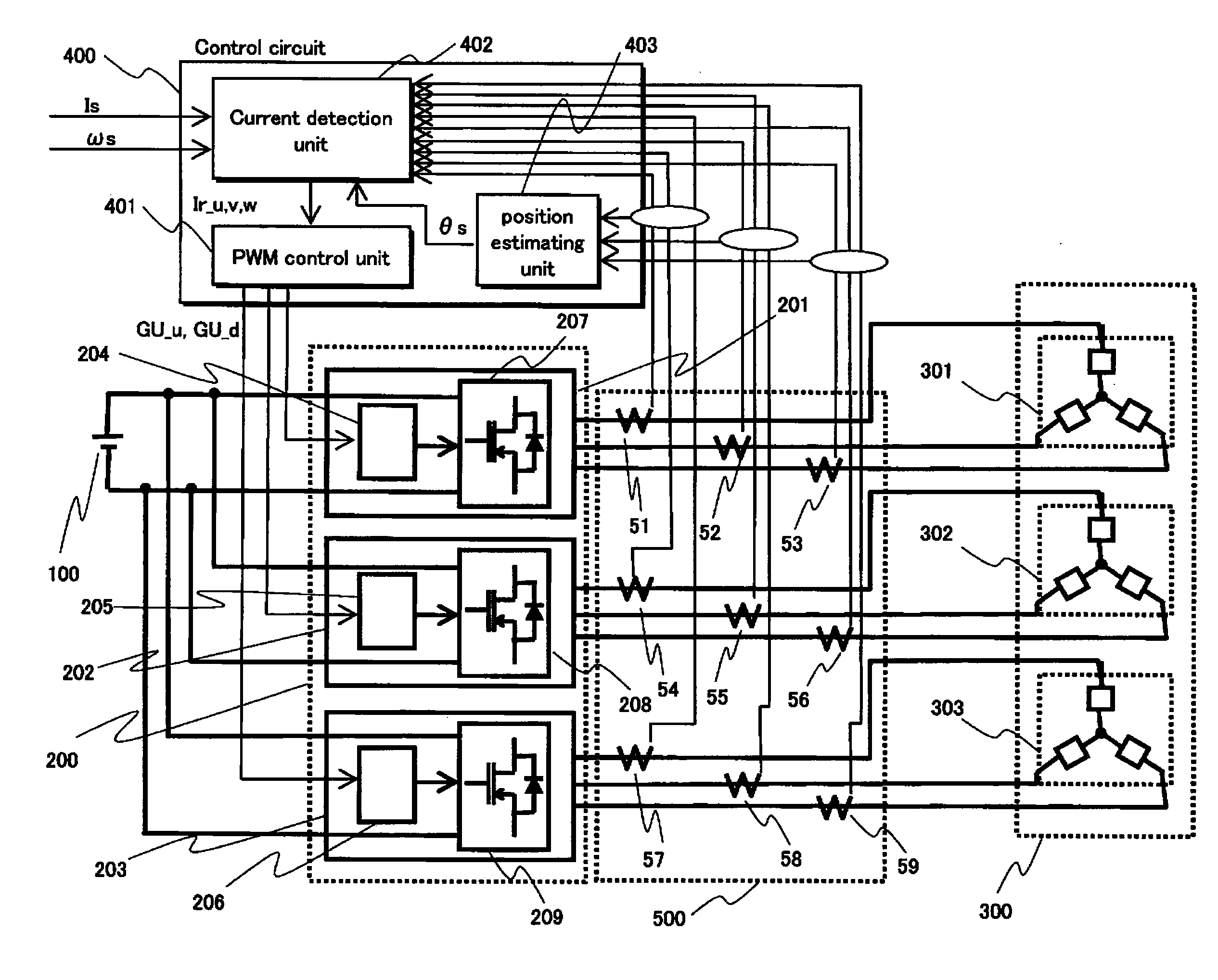
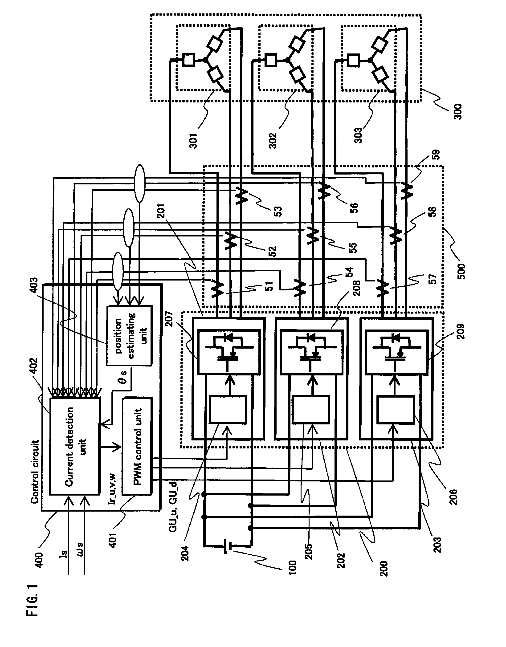
[0047]FIG. 1 shows an overall structure of a synchronous motor drive system pertaining to Embodiment 1 of the present invention.

[0048]The synchronous motor drive system includes a DC power source 100, an inverter group 200, a synchronous motor 300, a control circuit 400 and a current detection module 500.

[0049]The DC power source 100 provides direct current to the inverter group 200.

[0050]The inverter group 200 includes three-phase inverters 201, 202 and 203. Each of the three-phase inverters 201, 202 and 203 performs DC-AC conversion according to a gate control signal from the control circuit 400, and provides three-phase alternate current to the synchronous motor 300. The three-phase inverter 201, 202 and 203 are composed of power circuits 207, 208 and 209 and gate drive circuits 204, 205 and 206 corresponding to the power circuits, respectively. All the switching devices included in the three-phase inverters 201, 202 and 203 are included in a single module.

[0051]The synchronous m...

modification 1

of Embodiment 1

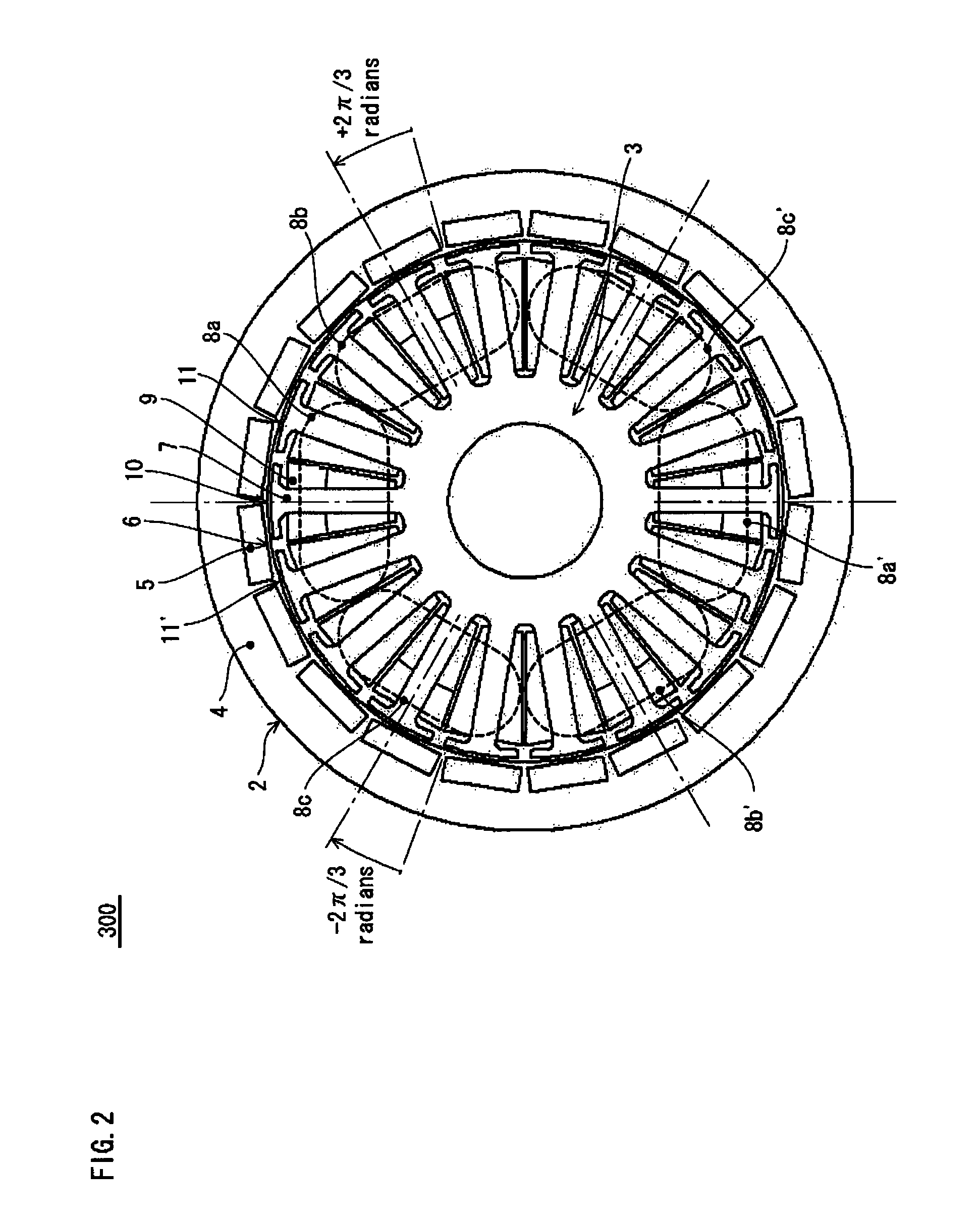
[0103]In the synchronous motor drive system pertaining to Embodiment 1 of the present invention, it is preferable that currents that are out of phase with each other are applied to the coil terminals of the synchronous motor. The following explains an example method for applying a current to the synchronous motor 300 to drive it to rotate. The structure of the synchronous motor 300 is shown in FIG. 2 and FIG. 3.

[0104]FIGS. 14A-14C show positional relationships between the stator and the rotor of Embodiment 1 of the present invention. FIG. 14A-14C show the positional relationship in the case where the rotor is rotated anti-clockwise by 2° in mechanical angle (i.e. π / 9 radians in electrical angle) at a time. FIG. 15 shows the temporal change of the currents applied by the three-phase inverters to the stator coils. The time points (a), (b) and (c) in FIG. 15 correspond to the positional relationships shown in FIG. 14A, FIG. 14B and FIG. 14C, respectively.

[0105]In FIG. 2 ...

modification 2

of Embodiment 1

[0113]A description is made below of a modification in which the present invention is applied to a synchronous motor drive system including two inverters. FIG. 16 shows an overall structure of a synchronous motor drive system pertaining to this modification.

[0114]In the synchronous motor drive system pertaining to this modification, the inverter group 200, the synchronous motor 300, the control circuit 400 and the current detection module 500 included in the system shown in FIG. 1 are replaced with a inverter group 210, a synchronous motor 304, a control circuit 404 and a current detection module 501, respectively. The following explains the differences form the structure shown in FIG. 1.

[0115]The inverter group 210 has the same structure as the inverter group 200 except that the three-phase inverter 203 is removed.

[0116]The synchronous motor 304 includes two three-phase coils 305 and 306.

[0117]The control circuit 404 has the same structure as the control circuit 400 ...


PUM


Abstract

The present invention aims to provide a synchronous motor drive system that is capable of suppressing ripples in current while reducing switching loss. The system includes three-phase inverters 201-203, a control circuit 400 for controlling the operations of the three-phase inverters and a synchronous motor 300 including a plurality of three-phase coils. To control the operations of the three-phase inverters, the control circuit 400 causes the three-phase inverters 201 and 203 and the three-phase inverter 202 to use different carrier frequencies to generate three-phase AC power, and each of the three-phase inverters supplies a different one of the three-phase coils with three-phase AC power.

Description

TECHNICAL FIELD[0001]The present invention relates to synchronous motor drive systems, and particularly to technology for controlling inverters for supplying driving power to synchronous motors.BACKGROUND ART[0002]In the use of a synchronous motor, it is required to boost the total efficiency of a synchronous motor drive system for driving the synchronous motor. To achieve a high efficiency, technology called Pulse Width Modulation control (hereinafter referred to as “the PWM control”) is often used in three-phase inverters for supplying driving power to a synchronous motor, for example.[0003]Meanwhile, due to development of semiconductor technology, synchronous motors have been commonly used as vehicle motors in recent years, in view of their reliability, controllability, efficiency, etc., even though the power source of a vehicle motor is a battery, which is a DC power source. In such cases, a high torque is required as well as a high efficiency.[0004]Generally, to increase the to...

Claims


Application Information

Patent Timeline
Patent Type & Authority Patents(United States)
IPC IPC(8): H02P25/22H02P9/04H02P27/06
CPCH02K3/28H02P25/22H02P27/08H02K11/0073H02K21/22H02K2213/03H02K2213/06H02K11/33
Inventor TAGOME, MASAKI
Owner PANASONIC CORP
Why Eureka
Try Eureka