Reflective liquid crystal panel

a liquid crystal panel and reflection technology, applied in non-linear optics, instruments, optics, etc., can solve the problems of low static contrast, slow response speed, low reflectance, etc., and achieve the effect of faster response time and higher image contrast and reflectan

Active Publication Date: 2013-03-26
HIMAX DISPLAY INC
View PDF6 Cites 0 Cited by
  • Summary
  • Abstract
  • Description
  • Claims
  • Application Information

AI Technical Summary

Benefits of technology

[0008]An aspect of the invention provides a reflective liquid crystal panel having a substantially higher image contrast and reflectance, as well as a faster response time.
[0014]In summary, the invention discussed in the embodiments thereof has at least one of the following advantages. Since the twisted angle of the liquid crystal layer is substantially between 68 degrees and 85 degrees, therefore the image contrast, reflectance, and response time of the reflective liquid crystal panel are enhanced. Moreover, the reflective liquid crystal panel may be configured to employ a beam splitter device such that light passing through the first alignment layer has the first polarization direction, and an angle α is formed between the first polarization direction and the first alignment direction, in which the range of the angle α is substantially between a predetermined range. Accordingly, the image contrast, reflectance, and response time of the reflective liquid crystal panel may be further enhanced.
[0015]Furthermore, by suitably designing the thickness of the liquid crystal layer and the refractive indices of the liquid crystal molecules, such that the phase retardation of the liquid crystal layer is within a predetermined range, and in conjunction with the aforementioned parameter settings (e.g., the values of the angle α and the twisted angle φ), besides being capable of enhancing the image contrast, reflectance, and response time of the reflective liquid crystal panel, the overall polarization conversion efficiency thereof is increased by at least 7.9%, thereby obtaining a preferred optical performance and electrical characteristic.

Problems solved by technology

However, when the LCOS device employs nematic liquid crystal molecules, usually four issues are inherent in the device: 1) low static contrast, 2) low reflectance, 3) need of compensation films to enhance contrast, and 4) slow response speed.
Moreover, when maintaining high contrast, a phase retardation of the liquid crystal layer needs to be increased correspondingly, and doing so increases cell gaps, thereby slowing down the response speed.
Hence, imminent issues for the reflective display device include solving the aforementioned problems while achieving high image contrast and reflectance, as well as fast response time.

Method used


Image

  • Reflective liquid crystal panel
  • Reflective liquid crystal panel
  • Reflective liquid crystal panel

Examples


Embodiment Construction

[0024]It is to be understood that both the foregoing and other detailed descriptions, features and advantages are intended to be described more comprehensively by providing an embodiment accompanied with figures hereinafter. The language used to describe the directions such as up, down, left, right, front, back or the like in the reference drawings is regarded in an illustrative rather than in a restrictive sense. Thus, the language used to describe the directions is not intended to limit the scope of the invention.

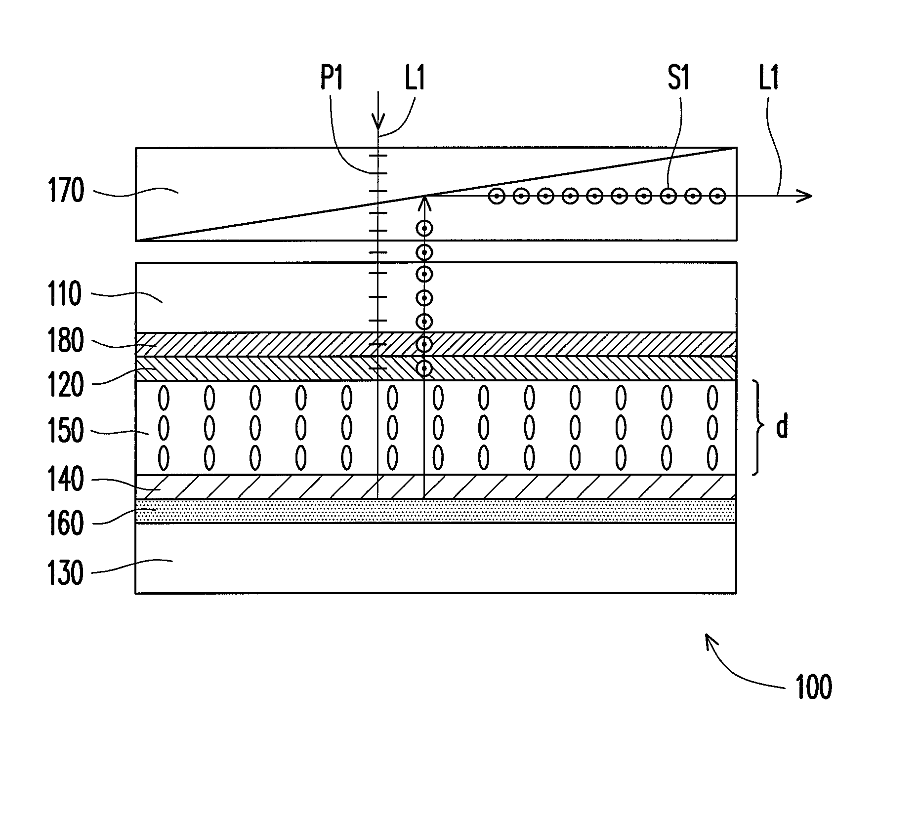
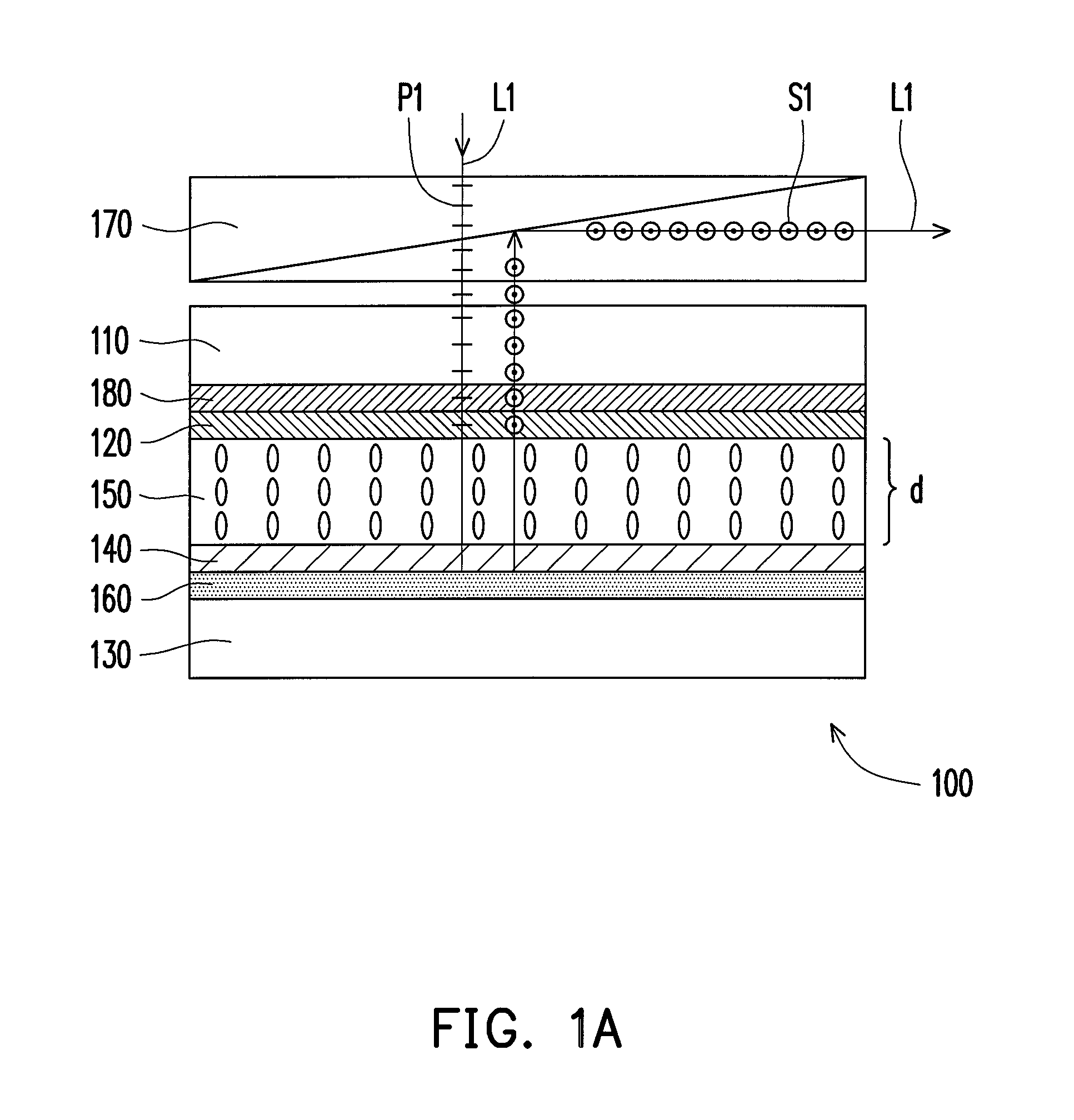
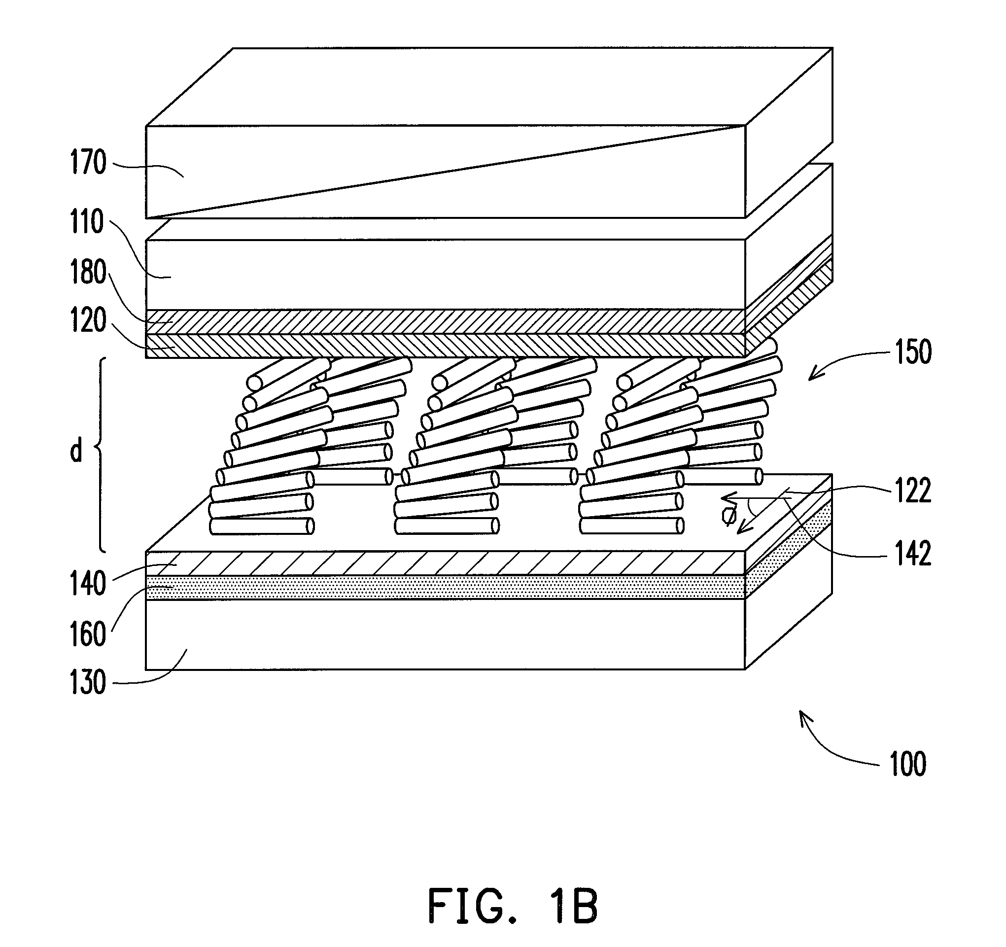
[0025]FIG. 1A is a schematic side view of a reflective liquid crystal panel in accordance with an embodiment of the invention. FIG. 1B is a perspective view of the reflective liquid crystal panel depicted in FIG. 1A. FIG. 2 is a schematic view of a light path transmitted in the reflective liquid crystal panel depicted in FIG. 1B. Referring to FIGS. 1A, 1B and 2, a reflective liquid crystal panel 100 of the present embodiment includes a first substrate 110, a first alignme...


PUM

PropertyMeasurementUnit
included angleaaaaaaaaaa
twisted angleaaaaaaaaaa

Abstract

A reflective liquid crystal panel including a first substrate, a first alignment layer, a second substrate, a second alignment layer, a liquid crystal layer and a reflection layer is provided. The first alignment layer disposed on the first substrate has a first alignment direction. The second substrate is opposite to first substrate. The second alignment disposed on the second substrate has a second alignment direction, wherein an included angle between the first alignment direction and the second alignment direction is substantially between 68 degrees and 85 degrees. The liquid crystal layer is disposed between the first substrate and the second substrate. The first alignment layer and the second alignment layer align the liquid crystal so that the liquid crystal layer has a twisted angle, wherein the twisted angle and the included angle are substantially the same. The reflection layer is disposed between the second alignment layer and the second substrate.

Description

CROSS-REFERENCE TO RELATED APPLICATION[0001]This application claims the priority benefit of U.S. provisional application Ser. No. 61 / 265,755, filed on Dec. 2, 2009. The entirety of the above-mentioned patent application is hereby incorporated by reference herein and made a part of specification.BACKGROUND OF THE INVENTION[0002]1. Field of the Invention[0003]The invention relates generally to a liquid crystal panel, and more particularly to a reflective liquid crystal panel.[0004]2. Description of Related Art[0005]Recently, developments of pico projection techniques have caught the attention of many watchers, as these devices (or mini projectors) have gradually become the mainstream for the future personal digital market. As all types of electronic products are being developed towards high speed, high efficiency, light weight and compact size, pico projectors have advantages of high portability and not being limited by sites of operation. Thus in the future, pico projectors may be em...

Claims


Application Information

Patent Timeline
Patent Type & Authority Patents(United States)
IPC IPC(8): G02F1/1335
CPCG02F1/1337G02F1/133553G02F2001/13355G02F1/13355
Inventor LI, YUET WINGFAN-CHIANG, KUAN-HSU
Owner HIMAX DISPLAY INC
Why Eureka
Try Eureka