Duty cycle adjusting circuit of a lighting system and method thereof

a technology of adjusting circuit and lighting system, which is applied in the direction of instruments, light sources, electroluminescent light sources, etc., can solve the problems of increasing cost, complicated adjusting circuit, and inability to fix the worn stability of intensity or color temperature, and achieves stable color temperature and simplified circuit complexity.

Inactive Publication Date: 2013-04-02
UPEC ELECTRONICS CORP
View PDF4 Cites 2 Cited by
  • Summary
  • Abstract
  • Description
  • Claims
  • Application Information

AI Technical Summary

Benefits of technology

[0007]Another aspect of the present invention is to adjust the duty cycle of the driving currents which drives the light emitting device of the first color and light emitting device of the second color to emit light respectively, and make the light within a predetermined range of color temperature to provide a stable light source with stable color temperature.
[0008]Another aspect of the present invention is to apply a sensing unit for sensing light of various colors for adjusting the intensity values to simplified circuit complexity.

Problems solved by technology

The conducting time and intensity of these LEDs of red, blue and green colors are controlled respectively, but such controlling mechanism is designed only for typical circumstances, and is unable to fix the worn stability of the intensity or color temperature harmed by high temperature or natural aging after used for a long time.
The illuminating intensity should be adaptively adjusted on a real-time basis, however, such mechanism requires numerous light sensors and also make the adjusting circuit complicated, both of which increase the cost.
Meanwhile, new problems may occur, such as the limited duty cycle and decreased lighting efficiency, the system disclosed in U.S. Pat. No. 7,397,205 faces, which corrects intensity with current value.

Method used


Image

  • Duty cycle adjusting circuit of a lighting system and method thereof
  • Duty cycle adjusting circuit of a lighting system and method thereof
  • Duty cycle adjusting circuit of a lighting system and method thereof

Examples


Embodiment Construction

[0016]In the following description, numerous details are set forth in order to provide a thorough understanding of the present invention with reference to drawings which are not drawn in an exact ratio. It will be appreciated by one skilled in the art that variations of these specific details are possible while still achieving the results of the present invention. In other instances, well-known backgrounds are not described in detail in order not to unnecessarily obscure the present invention.

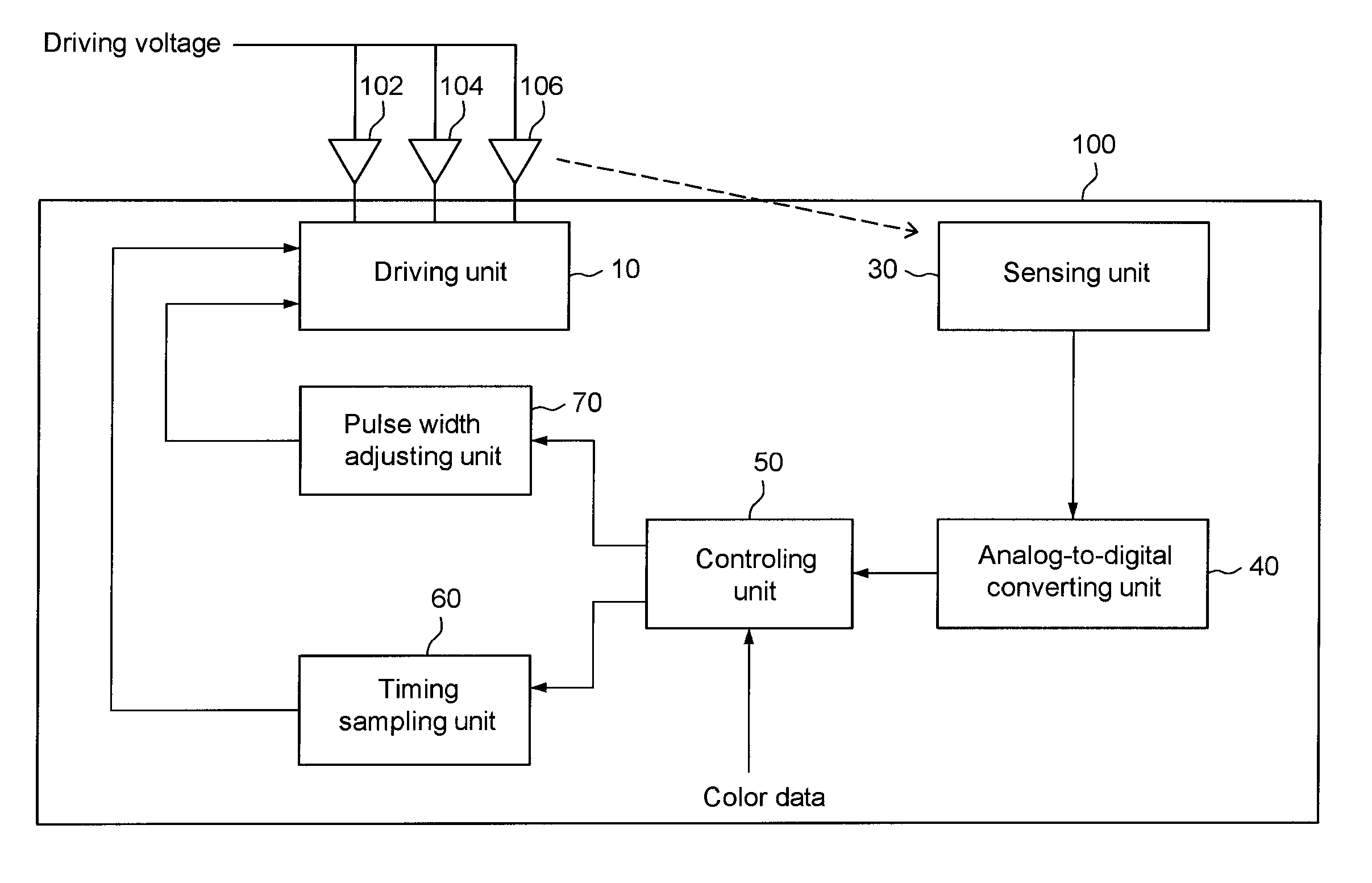
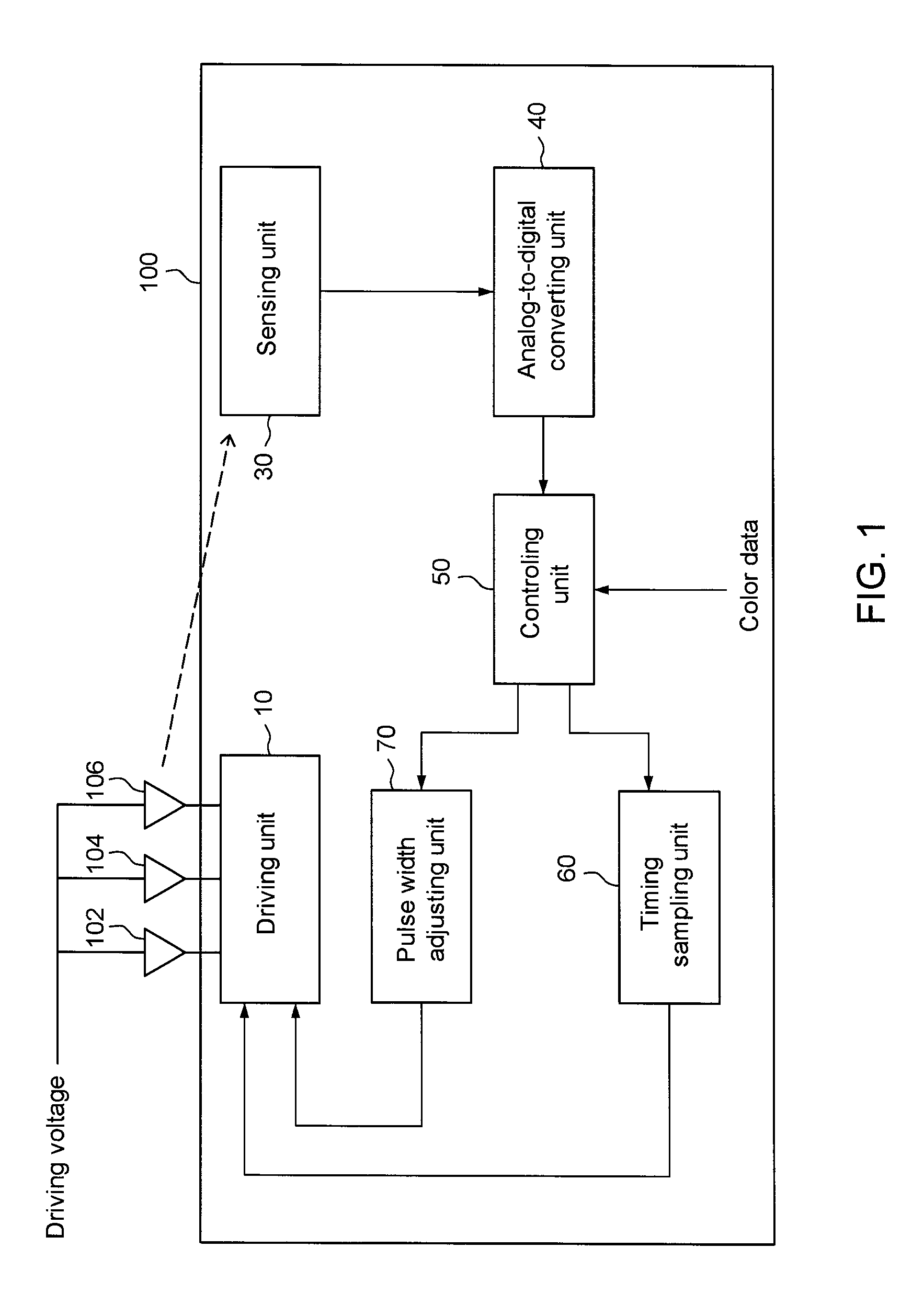
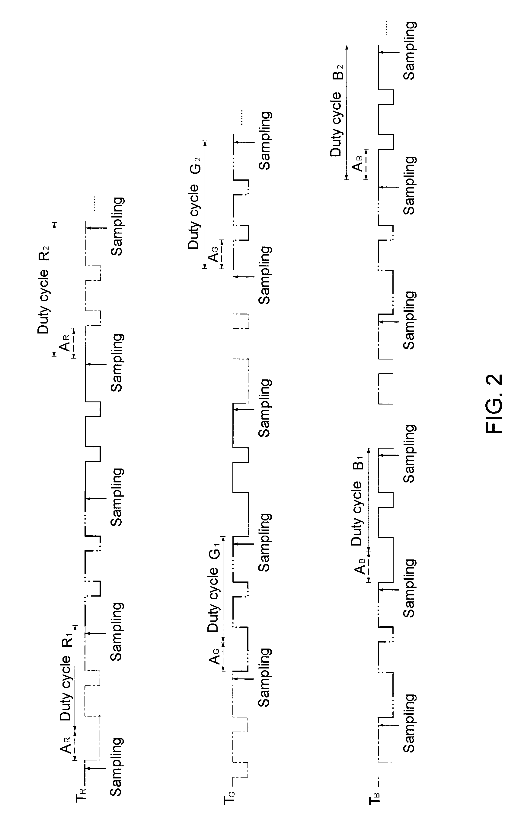
[0017]Please refer to FIG. 1 which shows a block diagram of a duty cycle adjusting circuit of a lighting system in an embodiment according to one aspect of the present invention. As shown, the duty cycle adjusting circuit 100 comprises a driving unit 10, a sensing unit 30, an analog-to-digital converting unit 40, a controlling unit 50, a timing sampling unit 60, and a pulse width adjusting unit 70. In the present embodiment, the duty cycle adjusting circuit 100 optionally comprises a storing un...


PUM


Abstract

The present disclosure relates to a duty cycle adjusting circuit of a lighting system and method thereof for sensing light of a first color and a second color emitted by a light emitting device of the first color and a light emitting device of the second color to generate corresponding intensity values. Then a first pulse width correcting value and a second pulse width correcting value can be calculated for adjusting a first duty cycle and a second duty cycle of a driving current to adjust the illuminating intensity of the light emitting devices of the first and the second colors. Through these adjusting steps, the light of the first and the second colors is within a predetermined range of color temperature. Therefore, light source for stable light in color temperature is provided.

Description

RELATED APPLICATION[0001]The present application claims priority under 35 U.S.C. 119(a) to Taiwan application number 098133454 filed on Oct. 1, 2009, which is incorporated herein by reference in its entirety as if set forth in full.FIELD OF THE INVENTION[0002]This invention relates to a duty cycle adjusting circuit of a lighting system and method thereof, and more particularly to a duty cycle adjusting circuit of a lighting system and method thereof regarding intensity and signals for colors.DESCRIPTION OF THE RELATED ART[0003]Light Emitting Diode (LED) is a cold light source which shows several great characteristics in power saving, device consumption, trigger time, mercury content and lifetime. Since the breakthrough for blue LED had been presented to the modern technology in late twentieth century, LEDs of various colors that emit light with high intensity are broadly applied in displays, projectors, lighting apparatus, etc. Now, though the LED is the light source to draw everyon...

Claims


Application Information

Patent Timeline
Patent Type & Authority Patents(United States)
IPC IPC(8): H05B37/02
CPCH05B33/086H05B45/22H05B45/325H05B45/20
Inventor TENG, CHIA-SHENTUNG, TZE-CHINGCHUANG, CHUN-MING
Owner UPEC ELECTRONICS CORP
Why Eureka
Try Eureka