
Microscope lighting system with adjustable color temperature

A lighting system and microscope technology, applied in the microscope field, can solve the problems of large LED spacing, complex structure, and low optical utilization rate, and achieve the effects of stable color temperature, simple structure, and high optical utilization rate

Pending Publication Date: 2019-08-23
MOTIC CHINA GRP CO LTD
View PDF3 Cites 1 Cited by
  • Summary
  • Abstract
  • Description
  • Claims
  • Application Information

AI Technical Summary

Problems solved by technology

[0003] Existing illumination systems with adjustable color temperature for microscopes, such as Leica patent US 2008 / 0151368 Al, use the method of replacing the light source module to achieve color temperature adjustment, which is cumbersome to operate and cannot achieve continuous adjustment of color temperature, which affects observation efficiency
Patent CN102768402B discloses a microscope lighting system with continuously adjustable color temperature, which simply uses multiple LEDs with different color temperatures, but the LED spacing is large, the light mixing is uneven, and the optical utilization rate is low
Sunny’s patent CN107505697A discloses a microscope lighting system with continuously adjustable color temperature, using multiple LEDs with different color temperatures, combined with a plane light source made of a light guide plate and a diffuser plate, to achieve uniform light mixing, but the structure is complex and the optical utilization low rate

Method used


Image

  • Microscope lighting system with adjustable color temperature
  • Microscope lighting system with adjustable color temperature
  • Microscope lighting system with adjustable color temperature

Examples


Embodiment Construction

[0025] In order to enable those skilled in the art to better understand the present invention, the technical solution of the present invention will be further described below in conjunction with the accompanying drawings and embodiments.

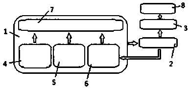
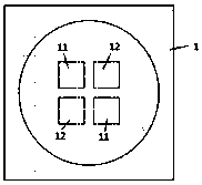
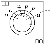
[0026] Such as figure 1 As shown, the implementation of the technical solution of the present invention includes: a control circuit 1, an LED light source 2, and a light collecting mirror 3, wherein the control circuit 1 further includes a color temperature control unit 4, a brightness control unit 5, a color temperature sensor 6, and a main control system unit 7 . The LED light source 2 is connected to the control circuit 1 , and the color temperature and brightness of the LED light source 1 can be controlled respectively through the adjustment knobs of the color temperature control unit 4 and the brightness control unit 5 . The light emitted by the LED light source 2 is irradiated on the specimen 8 after passing through the collecting len...


PUM


Abstract

The invention discloses a microscope lighting system with adjustable color temperature. The system comprises LED light sources, a control circuit and a man-machine interface, wherein the LED light sources are distributed symmetrically or uniformly in space, the control circuit can control the color temperature and luminance of the LED light sources simultaneously, and the control circuit is connected with the man-machine interface and the LED light sources respectively; the control circuit is composed of a color temperature adjustment unit, a luminance adjustment unit, a main control system unit and a color temperature sensor; and the main control system unit controls the luminance of LED chips with different color temperature through an LED light source driving module and adjusts the color temperature and luminance of microscope lighting. Through the microscope lighting system, the color temperature and luminance of white light illuminating a specimen surface can be adjusted accurately and effectively, and therefore a microscope can meet different environment or specimen requirements and achieve a good observation effect; and the microscope lighting system is simple in structure,high in optical utilization rate and more stable in color temperature.

Description

technical field [0001] The invention relates to the technical field of microscopes, in particular to a microscope lighting system with adjustable color temperature. Background technique [0002] Illumination system is an important part of modern microscope optical system. With the rapid development of science and technology, modern microscopes have higher and higher requirements for the illumination system. For different observation objects, light source illumination with suitable color temperature is required to obtain the best observation. Effect. [0003] Existing illumination systems with adjustable color temperature for microscopes, such as Leica patent US 2008 / 0151368 Al, use the method of replacing the light source module to achieve color temperature adjustment. The operation is cumbersome, and continuous adjustment of color temperature cannot be achieved, which affects observation efficiency. Patent CN102768402B discloses a microscope lighting system with continuous...

Claims


Application Information

Patent Timeline
Patent Type & Authority Applications(China)
IPC IPC(8): G02B21/06
CPCG02B21/06
Inventor 陈木旺耿义迪郑振彬
Owner MOTIC CHINA GRP CO LTD
Learn More