
System for inlet air mass enhancement

a technology of inlet air and enhancement, which is applied in the direction of combination devices, dispersed particle filtration, and using liquid separation agents, etc., can solve the problems of lower power output, higher inlet air temperature, and negative impact on the metallurgy of the compressor blade, so as to increase the air pressure, the humidity of the treated air is very high, and the capital and running costs are very high

Inactive Publication Date: 2013-04-09
FREUDENBERG FILTRATION TECH INDIA PVT LTD
View PDF14 Cites 127 Cited by
  • Summary
  • Abstract
  • Description
  • Claims
  • Application Information

AI Technical Summary

Benefits of technology

(i) Consistent leading air temperature irrespective of ambient conditions.
(ii) Parasitic load of the cooling water is relatively small.
(i) Higher parasitic load compared to Fogging Systems
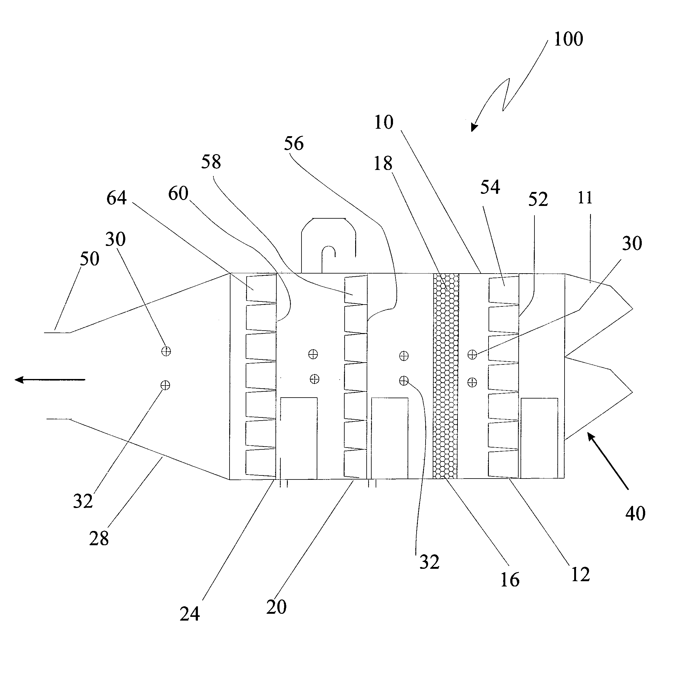
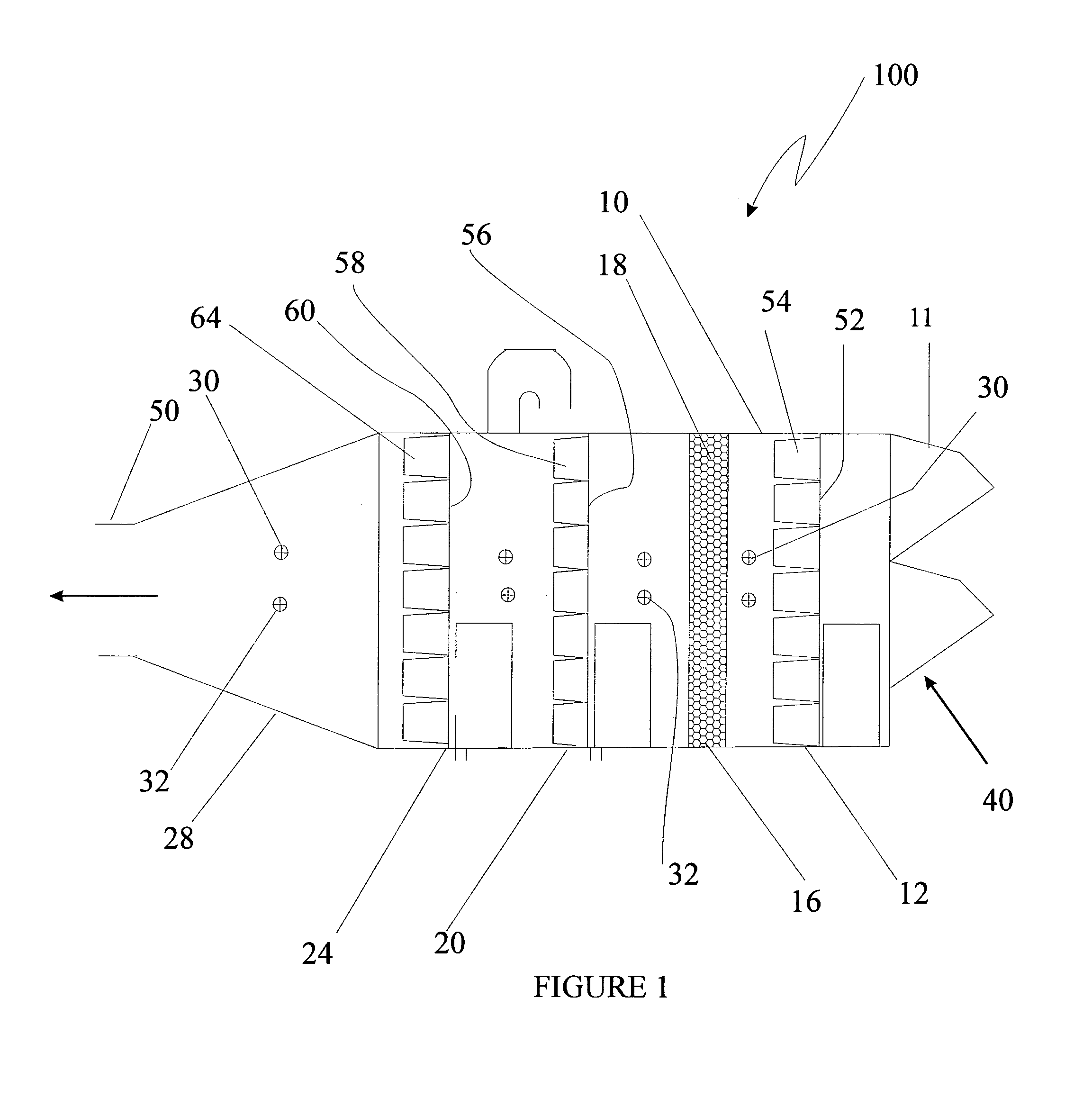
[0062]Typically the chilling tubes are coated with composite coatings adapted to improve heat transfer and reduce corrosion.

Problems solved by technology

This reduction of temperature is done by applying vapor absorption technology and using water as the chilling medium as other coolant has negative impact on the metallurgy of the compressor blades.
The amount of work the compressor consumes depends on ambient conditions such as air pressure, temperature and humidity.Gas turbines operate at a constant volume of air,Power generated depends upon the mass flow of air.Warm air is less dense than cold airHigher inlet air temperature results in lower power output.

Method used


Image

  • System for inlet air mass enhancement
  • System for inlet air mass enhancement
  • System for inlet air mass enhancement

Examples


example 2

Multi Filter Media System with Cooling

[0091]The above test was repeated after replacing all the filtration media with media of the same rating but the cooling zone was maintained at 15° C. Rate of cooling was adjusted to maintain a steady temperature of 15° C. in the cooling zone through out the test procedure. The flow rate through the filter was calculated and recorded. Typical flow rate achieved was 72,000 Cu.m / hr and the pressure drop was 40-50 Pa.

[0092]Tests as above conclusively prove that improved mass flow rate is achieved without any significant increase in pressure drop across the system.

[0093]Typically output of air achieved in accordance with this invention is clean, having particles not greater than the desired micron size at temperatures between 4 to 30 degrees Celsius where the delta P [loss in pressure] is low and the mass of air entering the process installation or apparatus is enhanced.

[0094]Thus mass of air is enhanced without significantly affecting the other par...


PUM

PropertyMeasurementUnit
sizeaaaaaaaaaa
temperatureaaaaaaaaaa
sizeaaaaaaaaaa

Abstract

A system and apparatus for enhancement of inlet air mass for processes by progressive filtration and intermediate cooling.

Description

FIELD OF INVENTION[0001]This invention relates to a system for inlet air mass enhancement.[0002]In particular, this invention relates to a system and apparatus for enhancement of inlet air mass in a turbo-machinery for air consuming processes.BACKGROUND OF THE INVENTION[0003]Improving the efficiency of any air consuming process like combustion, air separation, air compression for obtaining mechanical power is of considerable importance as this leads to saving of the fuel used for these processes. Most of the common fuels consumed are non replenish-able hydrocarbons. Inefficient burning of these fuels results in extensive pollution and is one of the main causes of global warming. If the air to fuel ratio is correctly maintained then the fuel is fully burned and causes little or no pollution to the atmosphere. Reducing the amount of fuel is one of the ways of improving the combustion process but leads to severe drop in power produced and is not feasible beyond certain levels. Improvin...

Claims


Application Information

Patent Timeline
Patent Type & Authority Patents(United States)
IPC IPC(8): B01D46/00
CPCB01D46/0024B01D46/0031B01D46/4218B01D46/521F02C7/055F02C7/143B01D2267/40B01D2275/10B01D46/64
Inventor RAJE, ATULSINGH, ANAND
Owner FREUDENBERG FILTRATION TECH INDIA PVT LTD
Learn More