
Display apparatus including plural pixel simultaneous sampling method and wiring method

Inactive Publication Date: 2007-05-15
SONY CORP
View PDF6 Cites 6 Cited by
  • Summary
  • Abstract
  • Description
  • Claims
  • Application Information

AI Technical Summary

Benefits of technology

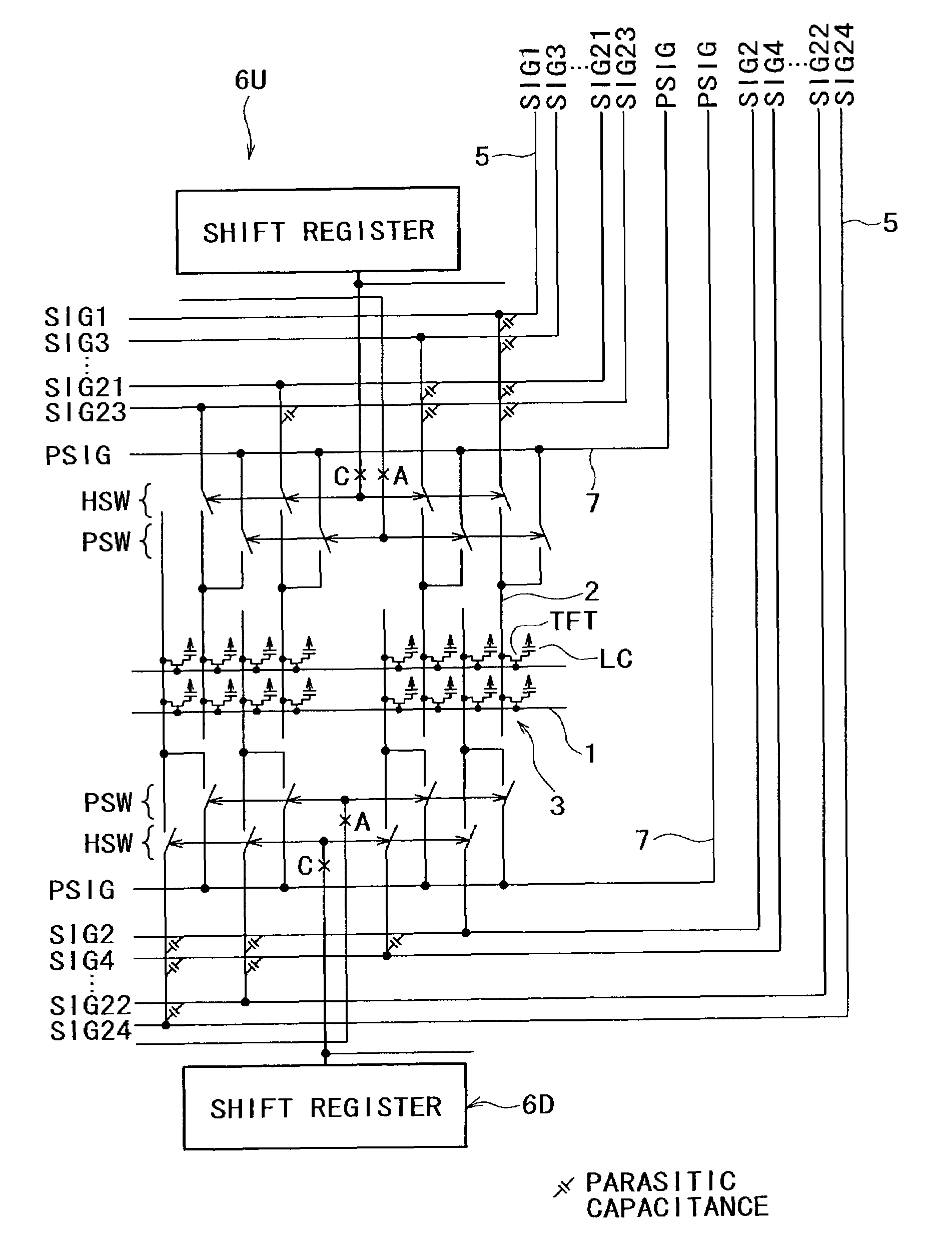
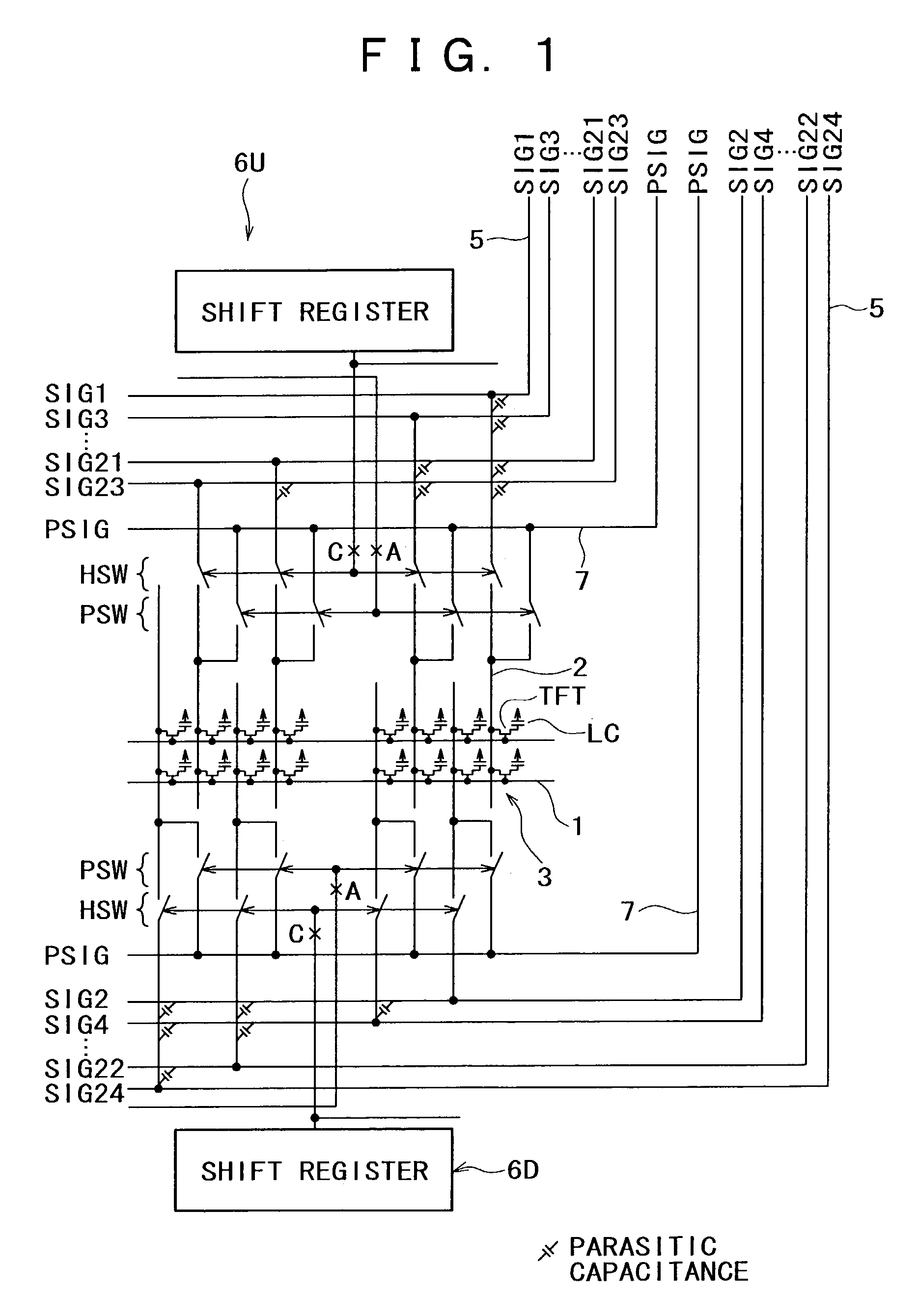
[0011]Preferably, one of each two adjacent ones of the signal lines is connected to one of the video lines of the upper side group while the other of the two adjacent signal lines is connected to one of the video lines of the lower side group. In this instance, each of the gate lines in the pixel array section may be disposed for a unit of two rows of the pixels between a pair of adjacent ones of the columns of the pixels, and the upper and lower side horizontal drive circuits may write video signals of the opposite polarities to each other to adjacent ones of the pixels connected to a same gate line through the corresponding ones of the signal lines. In this instance, the upper side horizontal drive circuit may sample the video signals of a same polarity from the video lines of the upper side group to corresponding ones of the signal lines while the lower side horizontal drive circuit samples the video signals of a same polarity from the video lines of the lower side group to corresponding ones of the signal lines thereby to suppress the level of parasitic capacitance to be felt by each of the upper and lower side video lines to raise a margin against ghost.
[0013]In the display apparatus, the video lines provided on a panel of the display apparatus are divided into two groups which are laid out on the upper and lower sides in the inside of the panel. In a corresponding relationship, also the switches of the sampling switch set and the horizontal drive circuits are disposed separately on the upper and lower sides, and the upper and lower side video lines are inputted to the upper and lower side horizontal drive circuits, respectively. With the layout of the display apparatus described, the number of signal lines which overlap with each of the video lines decreases to one half that of a conventional display apparatus. Consequently, also the parasitic capacitance decreases to one half, and therefore, a blunt of the video signals can be suppressed and the ghost margin can be increased.

Problems solved by technology

However, as the rise of the resolution of pixels further proceeds, it becomes impossible to assure a sufficient writing period of time with the simultaneous sample number of 12.
As the parasitic capacitance of each video line increases, the video signal SIG becomes blunt, which makes a cause of a display defect called ghost.
If the simultaneous sample number is doubled, then also the parasitic capacitance is doubled, and such blunt deformation of a video signal pulse as described above becomes worse and the ghost margin decreases.

Method used


Image

  • Display apparatus including plural pixel simultaneous sampling method and wiring method
  • Display apparatus including plural pixel simultaneous sampling method and wiring method
  • Display apparatus including plural pixel simultaneous sampling method and wiring method

Examples


Embodiment Construction

[0021]Referring to FIG. 1, there is shown a display apparatus to which the present invention is applied. In order to facilitate understanding, in FIG. 1, like elements to those of the conventional display apparatus shown in FIGS. 4 and 5 are denoted by like reference characters. The display apparatus shown includes a pixel array section, a horizontal drive circuit, a vertical drive circuit, sampling switch sets, video lines and precharge lines. However, the vertical drive circuit is not shown in FIG. 1 in order to simplify illustration. The pixel array section includes a plurality of gate lines 1 extending in the direction of a row, a plurality of signal lines 2 extending in the direction of a column, and a plurality of pixels 3 disposed in rows and columns at points at which the gate lines 1 and the signal lines 2 intersect with each other. Each of the pixels 3 is formed from a thin film transistor TFT and a liquid crystal cell LC. However, the present invention is not limited to t...


PUM


Abstract

A display apparatus employing a plural pixel simultaneous sampling method is disclosed wherein the parasitic capacitance of each wiring line is reduced to suppress a ghost. A sampling switch set includes switches which are connected to corresponding ones of signal lines and video lines. Upper and lower side horizontal drive circuits drive switches of the sampling switch set simultaneously to sample the video signals of systems to the corresponding signal lines, and perform sampling successively for each signal lines to write the video signals into pixels of the selected row. The video lines are divided into two groups of video lines disposed on the upper and lower sides. The upper side video lines are connected to corresponding even-numbered ones of the signal lines through the corresponding switches while the lower side video lines are connected to corresponding odd-numbered ones of the signal lines through the corresponding switches.

Description

[0001]This application claims priority to Japanese Patent Application Number JP2001-319266 filed Oct. 17, 2001 which is incorporated herein by reference.BACKGROUND OF THE INVENTION[0002]This invention relates to an active matrix display apparatus, and more particularly to improvements in or relating to a display apparatus that adopts a “plural pixel simultaneous sampling method” of writing a video signal at a time into a plurality of pixels.[0003]FIG. 4 shows a typical example of a conventional active matrix display apparatus. Referring to FIG. 4, the display apparatus 0 shown includes a pixel array section 9, a horizontal drive circuit 6, a pair of vertical drive circuits 4, and a precharge drive circuit 8. The pixel array section 9 includes gate lines 1 extending in the direction of a row, signal lines 2 extending in the direction of a column, and pixels 3 disposed at points at which the gate lines 1 and the signal lines 2 intersect with each other. The vertical drive circuits 4 a...

Claims


Application Information

Patent Timeline
IPC IPC(8): G09G3/36G02F1/133G09G3/20
CPCG09G3/20G09G2310/0248G09G2310/0275G09G2320/0223G09G2320/0257G09G2352/00
Inventor UCHINO, KATSUHIDEYAMASHITA, JUNICHI
Owner SONY CORP
Learn More