Systems and methods for imaging objects

a technology of imaging objects and systems, applied in the field of imaging systems and methods, can solve the problems of conflicting requirements between two modes, not the most optimal for either, etc., and achieve the effects of preventing blurring or smearing of letters, reducing noise, and high speed

Active Publication Date: 2013-04-09
FREEDOM SCI
View PDF8 Cites 2 Cited by
  • Summary
  • Abstract
  • Description
  • Claims
  • Application Information

AI Technical Summary

Benefits of technology

[0007]Low vision magnifying systems are used to view static images, such as photographs or medicine bottles (viewing mode), and to move across and read printed material, such as newspapers or magazines (reading mode). These two modes present conflicting requirements, especially for magnifying systems. The viewing mode requires very low noise, as any noise is appreciably increased during the magnification and contrast enhancement stages and detracts from the clarity of the image. The reading mode requires high speed exposures to prevent the blurring or smearing of the letters and images which makes them illegible while moving the device along the text being read. This means that the viewing and reading modes require different optimizations. In particular, the exposure for viewing static images should be one that minimizes noise, while the exposure for the reading mode must be fast to prevent blurring. Existing products select an exposure that is a compromise between these two modes and not the most optimal for either. Recognizing the differences between the two modes, this invention detects relative motion and dynamically determines which settings are most optimal for the mode that is being used.
[0009]At least one aspect of the present invention is directed to an imaging device. The imaging device may include a sensor to provide an image of an object. The sensor can have a sensor exposure time and a sensor gain and the image includes a plurality of frames, each of the plurality of frames that can depict at least a portion of the object. The imaging device may include a motion detector to determine whether there is movement of the at least a portion of the object between adjacent frames of the plurality of frames. The imaging device may also include a controller that can set the sensor exposure time to a first value in response to a determination by the motion detector that there is movement of the at least a portion of the object between adjacent frames. The controller can also set the sensor exposure time to a second value in response to a determination that there is no movement of the at least a portion of the object between adjacent frames. Further, the controller can adjust the sensor exposure time, the sensor gain, or both to maintain a luminance value of the plurality of frames at a target luminance value.
[0013]In various embodiments, during a period of time in which it is determined that there is movement of the at least a portion of the object between adjacent frames, the controller may maintain the sensor exposure time at the first value and may adjust the sensor gain to substantially maintain the luminance value of the plurality of frames at the target luminance value. During a first portion of a period of time in which it is determined that there is no movement of the at least a portion of the object between adjacent frames, the controller may maintain the sensor exposure time at the second value and may adjust the sensor gain to substantially maintain the luminance value of the plurality of frames at the target luminance value. During a second portion of the period of time in which it is determined that there is no movement of the at least a portion of the object between adjacent frames, the controller may maintain the sensor gain at a fixed gain value and to further adjust the sensor exposure time to a fixed exposure time value so that the luminance value of the plurality of frames is equal to the target luminance value. During a third portion of the period of time in which it is determined that there is no movement of the at least a portion of the object between adjacent frames, the controller may maintain the sensor gain at the fixed gain value, and may maintain the sensor exposure time at the fixed exposure time value.

Problems solved by technology

These two modes present conflicting requirements, especially for magnifying systems.
Existing products select an exposure that is a compromise between these two modes and not the most optimal for either.

Method used


Image

  • Systems and methods for imaging objects
  • Systems and methods for imaging objects
  • Systems and methods for imaging objects

Examples


Embodiment Construction

[0024]The systems and methods described herein are not limited in their application to the details of construction and the arrangement of components set forth in the description or illustrated in the drawings. The invention is capable of other embodiments and of being practiced or of being carried out in various ways. Also, the phraseology and terminology used herein is for the purpose of description and should not be regarded as limiting. The use of “including”“comprising”“having”“containing”“involving” and variations thereof herein, is meant to encompass the items listed thereafter and equivalents thereof as well as additional items.

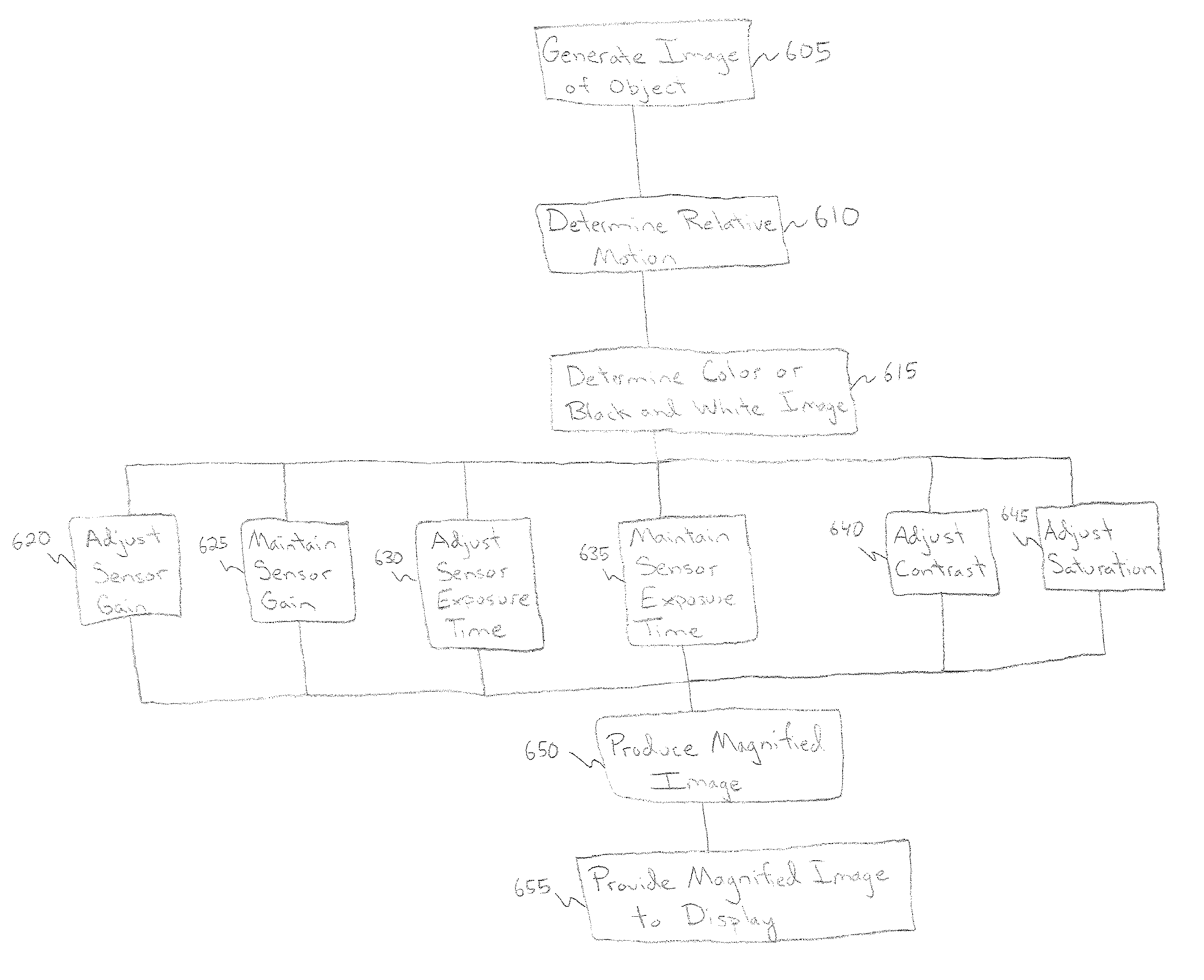
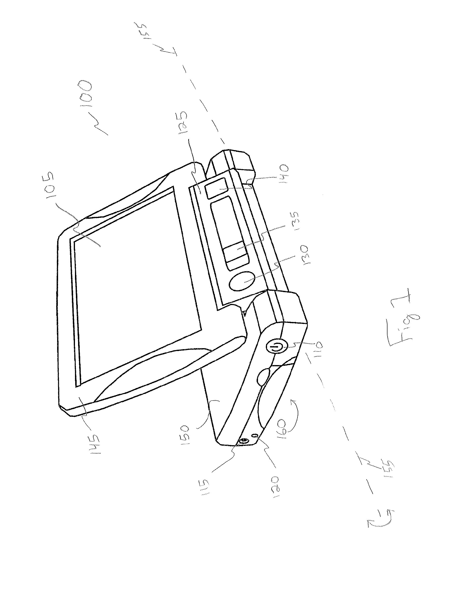
[0025]Various aspects and embodiments are directed to imaging objects. For example, and as discussed further below, an imaging device may capture or produce images of an object. These images, which may include a series of frames, may be enlarged to facilitate their viewing. When, for example, there is relative motion between an imaging device and an ob...


PUM


Abstract

Systems and methods for imaging objects are provided. An imaging device includes a sensor to provide an image of an object. The sensor can have a sensor exposure time and a sensor gain and the image includes a plurality of frames, each of the plurality of frames that can depict at least a portion of the object. The imaging device includes a motion detector to determine whether there is movement of the at least a portion of the object between adjacent frames of the plurality of frames. The imaging device also includes a controller. The controller can set the sensor exposure time to a first value in response to a determination by the motion detector that there is movement of the at least a portion of the object between adjacent frames. The controller can also set the sensor exposure time to a second value in response to a determination that there is no movement of the at least a portion of the object between adjacent frames. The controller can also adjust the sensor exposure time, the sensor gain, or both to maintain a luminance value of the plurality of frames at a target luminance value.

Description

RELATED APPLICATIONS[0001]This application claims priority under 35 U.S.C. §119 or 365 to U.S. Provisional Patent Application No. 61 / 099,185, filed Sep. 22, 2008. The entire teaching of that application is incorporated herein by reference.BACKGROUND OF THE INVENTION[0002]1. Field of Invention[0003]Embodiment of the present invention are directed to imaging systems and methods, and more particularly to imaging systems and methods capable of addressing the needs of persons with at least some degree of visual impairment.[0004]2. Discussion of Related Art[0005]Many people suffer from vision impairments or some degree of vision loss. With an aging population, the number of people with at least some form of age related vision loss or impairment continues to grow. Industrial accidents, hereditary conditions, and diseases such as diabetes result in degrees of vision loss or impairment that can afflict younger populations as well.[0006]Viewing text documents and other images or objects is a ...

Claims


Application Information

Patent Timeline
Patent Type & Authority Patents(United States)
IPC IPC(8): H04N5/232
CPCG09B21/008H04N5/144H04N5/2352H04N5/23296H04N5/243H04N5/23251H04N5/2353H04N23/72H04N23/76H04N23/73H04N23/69H04N23/681
Inventor CONARD, TODD
Owner FREEDOM SCI
Why Eureka
Try Eureka