

Dual path multi-mode power amplifier routing architecture
a power amplifier and multi-mode technology, applied in the direction of substation equipment, antennas, electrically long antennas, etc., can solve the problems of significant challenges for wireless communications products, complex rf architectures of wireless products, etc., and achieve the effect of facilitating the sharing of rf input, reducing size and cost of multi-mode rf pa circuitry
- Summary
- Abstract
- Description
- Claims
- Application Information
AI Technical Summary
Benefits of technology
Problems solved by technology
Method used
Image

Examples
Embodiment Construction
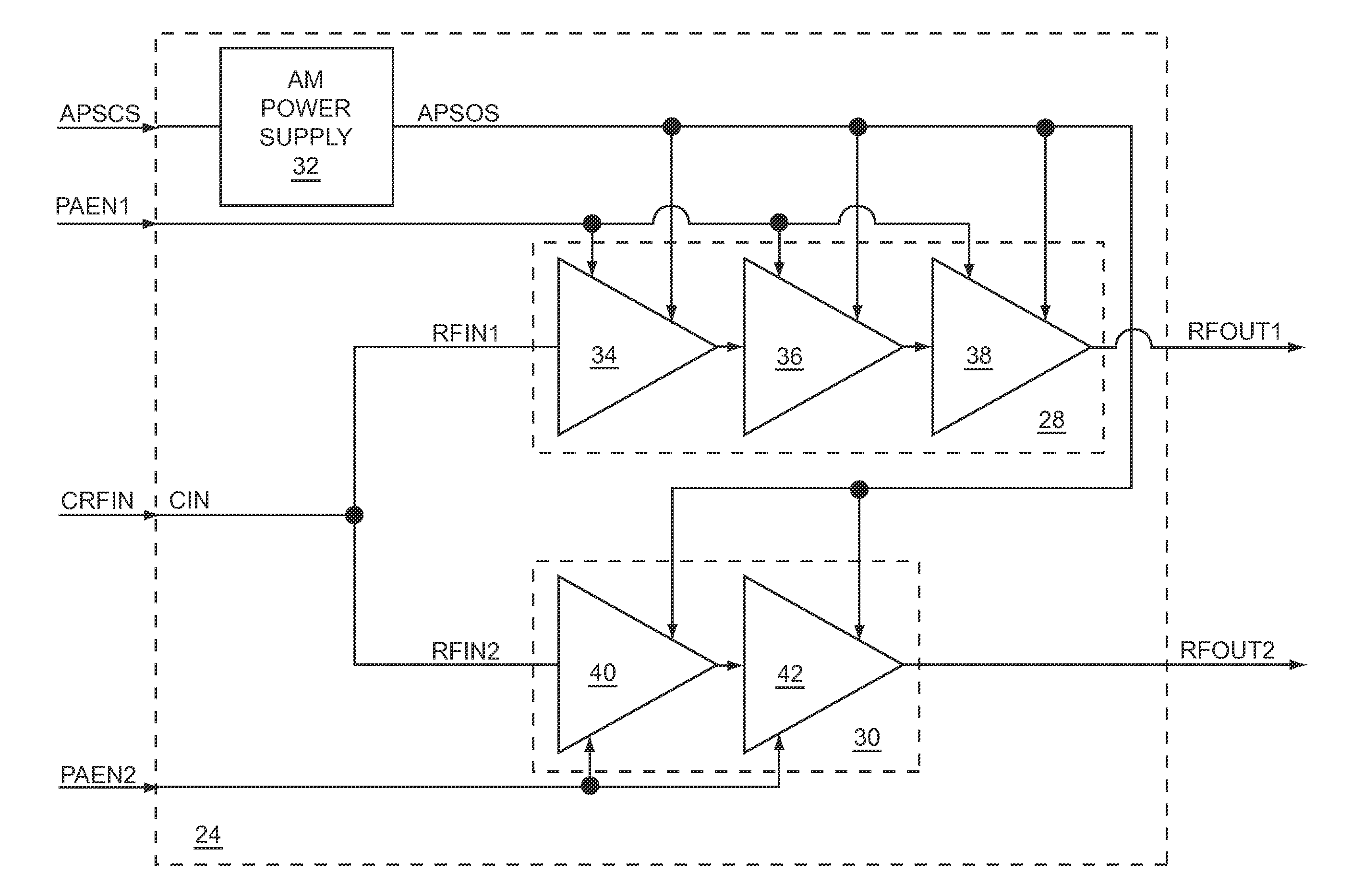
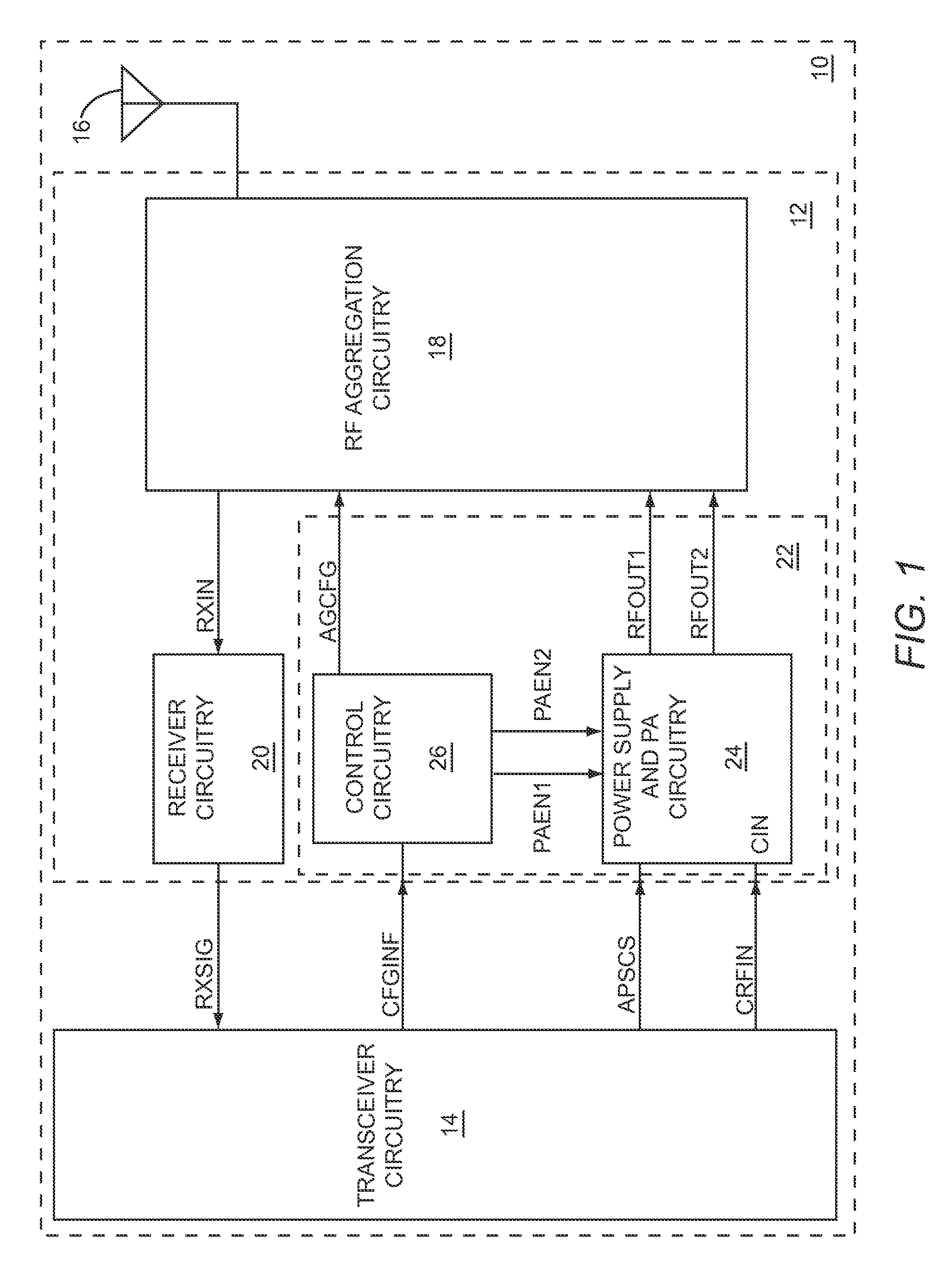
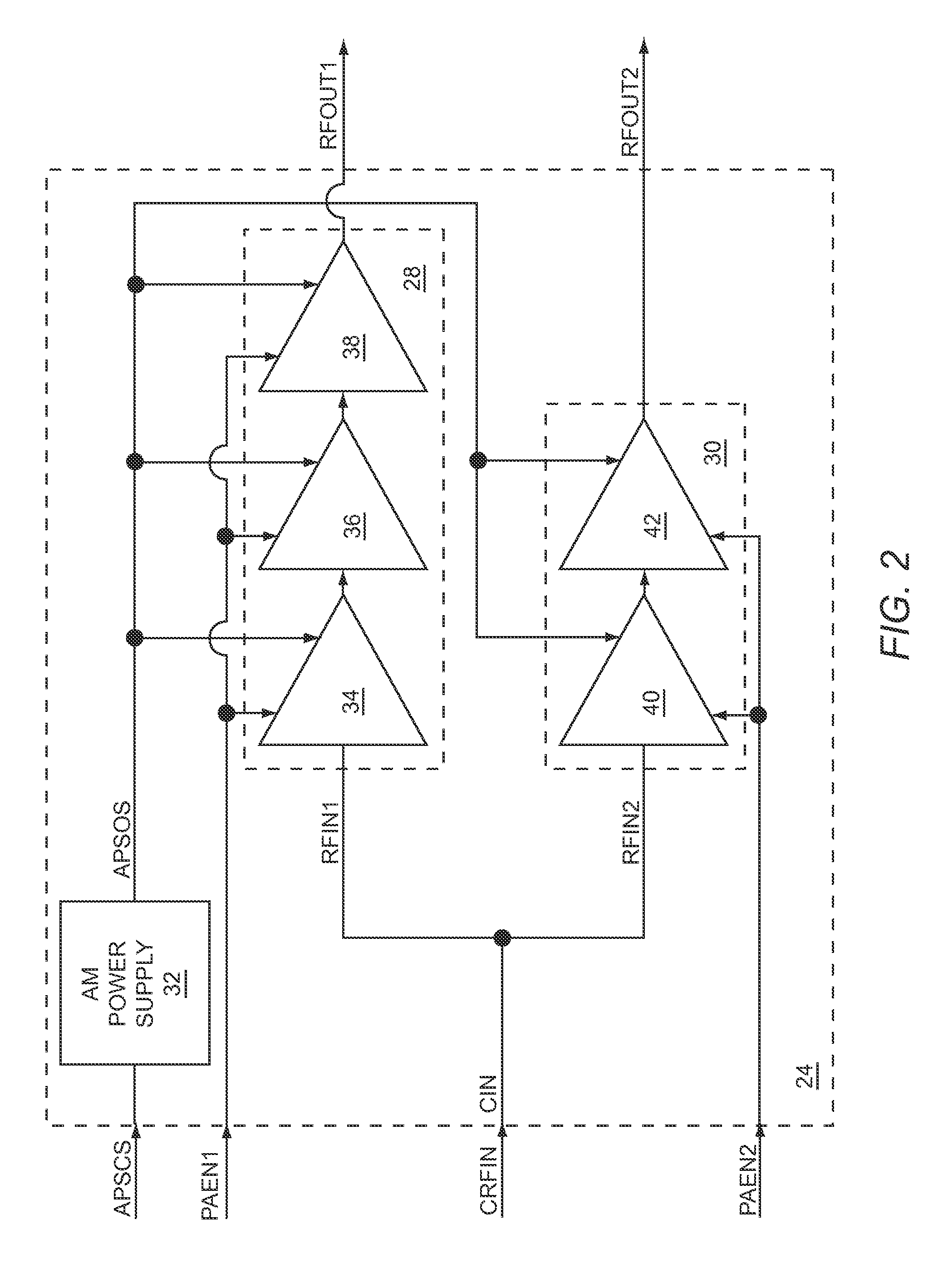
[0004]The present disclosure relates to multi-mode RF power amplifier (PA) circuitry that may include a first PA path and a second PA path, each of which is fed from a common RF input. During a first operating mode, the first PA path receives and amplifies a first RF input signal via the common RF input to provide a first RF output signal, and during a second operating mode, the second PA path receives and amplifies a second RF input signal via the common RF input to provide a second RF output signal. To facilitate sharing of the common RF input, during the first operating mode, the second PA path is substantially de-coupled from the common RF input, and during the second operating mode, the first PA path is substantially de-coupled from the common RF input. By sharing the common RF input, size and costs of the multi-mode RF PA circuitry may be reduced.
[0005]In one embodiment of the present disclosure, during both the first and the second operating modes, transceiver circuitry may p...
PUM
 Abstract
Description
Claims
Application Information