Firearm safety lock

a safety lock and firearm technology, applied in the field of firearms and biometric systems, can solve the problems of manufacturers being prohibited from selling handguns in some jurisdictions without a license, the harm resulting from inappropriate use of firearms is compounded or exacerbated, and the potential for abuse and misus

Inactive Publication Date: 2013-04-16
INTELLIGUN
View PDF36 Cites 31 Cited by
  • Summary
  • Abstract
  • Description
  • Claims
  • Application Information

AI Technical Summary

Problems solved by technology

As with any tool with destructive capabilities, there is a potential for abuse and misuse.
Because of its lethality, the harm resulting from inappropriate uses of firearms are compounded or exacerbated.
Still further, manufacturers are prohibited from selling handguns in some jurisdictions without meeting safety requirements such as loaded chamber indicators, magazine disconnects, passing drop tests.
Despite these wide-ranging measures, many may still be apprehensive of firearm ownership, both personally and by others.
For instance, spouses or other family members may feel uncomfortable with keeping a loaded firearm in the home, no matter how remote the possibility of accidental shootings under proper storage conditions.
Indeed, there have been incidents of a child somehow gaining access to a firearm and accidentally discharging it, resulting in injuries to bystanders.
Furthermore, there are also worries that a firearm carried on the person may get used by a perpetrator against the actual owner after being inadvertently let go during a physical altercation.
Due to these concerns, ordinary law-abiding citizens may forego purchasing a firearm, and even when able to do so under local laws, not carry it while going about their daily lives.
Although legislated a “gun free zone,” educational institutions may be vulnerable to mass shooting attacks, necessitating armed guards.
However, some parents may oppose this, citing the inherent dangers of firearms and the risk of it being taken from the guard to be used against students.
Police officers are often required to use multi-level retention holsters that require the skillful manipulation of buttons and latches to release, and involve fine motor functions that may be difficult to perform under stress without substantial training.
Indeed, there are numerous reported incidents where the law enforcement officer is shot with his or her own firearm.
These objectives are seemingly exclusive of each other: safeties that can be readily disengaged tend to render the firearm unsafe overall for that very reason, while safeties and locks that robustly secure the firearm tend to be cumbersome and time-consuming to disengage.
Conventional designs are inevitably a compromise that emphasizes accessibility over safety, or vice-versa.
Although keyed locks are quick to open, in order to ensure that no unauthorized individuals access its contents, the keys must be kept secure, thereby increasing the likelihood of loss or damage.
Combination locks do not require keys, but the entry of the combination via numeric keypads and dials can take a significant amount of time.
All of these measures, including storage in a safe, unfortunately increase the length of time between detecting a threat and firing in self defense.
Considering the speed with which various crimes are carried out, the targeted victim is in a position of substantial disadvantage, particularly where the perpetrator has the advantage of the element of surprise.

Method used


Image

  • Firearm safety lock
  • Firearm safety lock
  • Firearm safety lock

Examples


first embodiment

[0065]Referring to FIG. 5 and FIG. 6A, the mainspring housing 88a further defines a second bore 118. The lock 72 includes a locking pin 120 that is retractable into and extendible out of the second bore 118. In the extended position, the locking pin 120 blocks the rotation of the grip safety 26. On the other hand, in the retracted position, no obstruction is presented against the grip safety 26, allowing free movement thereof.

[0066]Within the second bore 118, there is disposed an actuator 122 that retracts and extends the locking pin 120. Any type of actuator may be utilized, though in one embodiment, it is electromechanical. In this regard, the actuator 122 may be comprised of a servo motor 126 with a planetary gear that translates rotational motion to linear motion. It will be recognized by those having ordinary skill in the art, however, that the actuator 122 may be a solenoid, a stepper motor, a bimetallic strip, a piezoelectric actuator, or any other suitable electromagnetic de...

second embodiment

[0068]In some cases, there may be a need to externally override the actuator 122, and so the mainspring housing 88b defines an override key slot 128 through which a mechanical override 256 is accessed. According to one implementation, the mechanical override 256 includes a socket 258 that is mechanically linked to the actuator 122. By rotating the socket 258 with a key that is configured to be received therein, the telescoping shaft is retracted, thereby retracting the blocking wedge 254. Although one embodiment of the mechanical override 256 has been shown and discussed, those having ordinary skill in the art will recognize that other configurations are also possible.

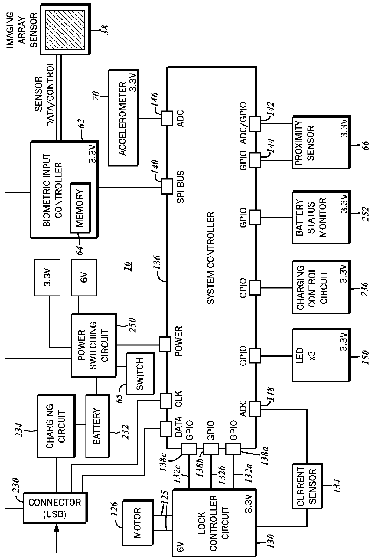
[0069]Referring again to the block diagram of FIG. 2, first and second electronic signals that drive the actuator 122 is generated by a lock controller circuit 130. More particularly, the lock controller circuit 130 is a conventional H-bridge circuit, which bi-directionally connects a voltage source to a load, that is,...


PUM


Abstract

A lock for a firearm with a grip safety, and a sear engageable to a biased hammer in a cocked position and releasable by a trigger is disclosed. The lock has a housing defining a first bore within which a mainspring that biases the hammer is received, as well as a second bore. There is a locking pin retractable into and extendible out of the second bore of the housing. When the locking pin is in an extended position, the grip safety is restricted to an engaged state, blocking movement of the trigger. An actuator disposed in the housing and cooperatively linked to the locking pin provides the motive force for retracting and extending the locking pin.

Description

CROSS-REFERENCE TO RELATED APPLICATIONS[0001]The present application relates to the concurrently filed co-pending application entitled “FIREARM LOCKING SYSTEM,” the disclosure of which is expressly incorporated by reference in its entirety herein.STATEMENT RE: FEDERALLY SPONSORED RESEARCH / DEVELOPMENT[0002]Not ApplicableBACKGROUND[0003]1. Technical Field[0004]The present disclosure relates generally to firearms and biometric systems, and more particularly to a firearm safety system that locks and prevents the operation of a firearm without valid biometric credentials. The present disclosure also relates to firearm locks that prevent the disengagement of safeties.[0005]2. Related Art[0006]Firearms are valuable tools that are commonly utilized for many legitimate purposes by civilians, military, and police alike. Chief among these purposes is personal defense, as firearms greatly level the field and equalize inherent power imbalances typical between criminal and potential victims. With...

Claims


Application Information

Patent Timeline
Patent Type & Authority Patents(United States)
IPC IPC(8): F41A17/56
CPCF41A17/066
Inventor KEMMERER, JASONMENDELSOHN, YISHAICOPE, CLINTON D
Owner INTELLIGUN
Why Eureka
Try Eureka