Electric connector

a technology of electric connectors and connectors, applied in the direction of securing/insulating coupling contact members, coupling device connections, electrical apparatus construction details, etc., can solve the problems of cover breaking off, limiting the surface of the cover carrying all the driving force, and not being beneficial to the life span of the produ

Inactive Publication Date: 2013-04-16
SUYING ELECTRCNICS (DONG GUAN) CO LTD
View PDF26 Cites 2 Cited by
  • Summary
  • Abstract
  • Description
  • Claims
  • Application Information

AI Technical Summary

Benefits of technology

[0008]The primary object of the present invention is to provide an electric connector to solve the problems of the prior art. The electric connector can disperse the driving force of the eccentric driving cam to the cover and the insulation base, proving a dual-stop effect and preventing the cover from bearing the applied force alone.
[0009]Another object of the present invention is that the direction of the applied force of the eccentric driving cam is the same as the sliding direction of the cover to effectively decrease the driving force of the eccentric driving cam. Only little torsion force is required to drive the electric connector.
[0016]Through the limit recess surrounding the axle hole of the insulation base, the eccentric driving cam can be stopped by the cover and the insulation base to disperse the driving force and to provide a dual-stop effect, preventing the cover from breaking off.
[0017]Through a metallic spacer received in an accommodation chamber of a cover platform of the cover, the metallic spacer has an opening and a protruding block which is located at a side of the opening. The protruding block corresponds to the limit block. The protruding block has two third limit surfaces at two sides thereof. When the eccentric driving cam is turned by a torsion force, the first stop surfaces of the eccentric action portion are against the third limit surfaces. When the eccentric driving cam is turned to a predetermined position, the eccentric driving cam is stopped by the third limit surfaces, the second limit surfaces and the first limit surfaces to disperse the driving force to the metallic spacer and to enhance the stop effect of the eccentric driving cam. Because the metal has a high hardness and doesn't deform and split easily, so the limit block made of a metallic material won't be broken off.

Problems solved by technology

However, the limit surfaces of the cover bear all the driving force.
When the force is applied too much, the cover may be broken off.
This is not beneficial to the life span of the product.

Method used


Image

  • Electric connector
  • Electric connector
  • Electric connector

Examples


Embodiment Construction

[0038]Embodiments of the present invention will now be described, by way of example only, with reference to the accompanying drawings.

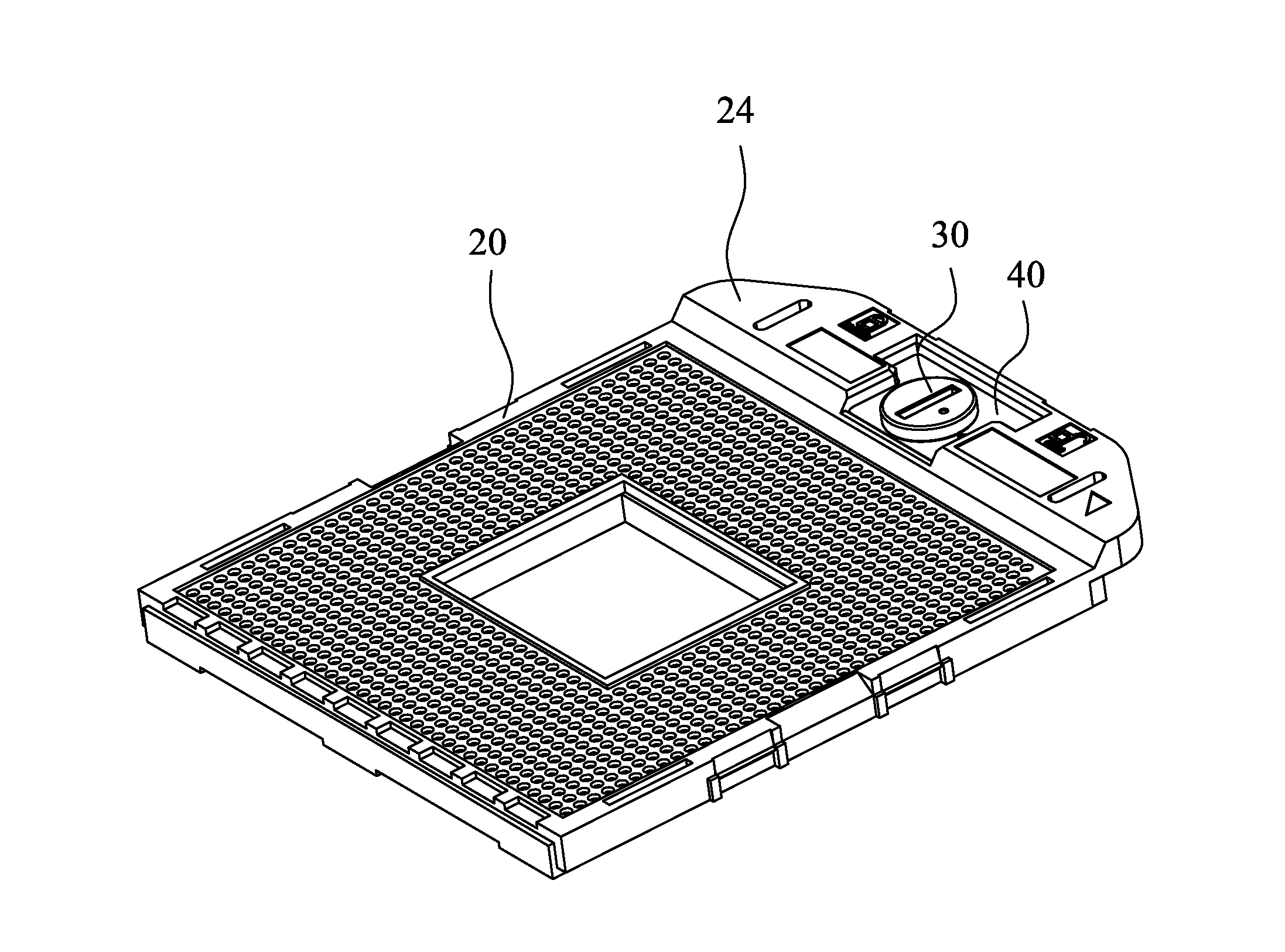
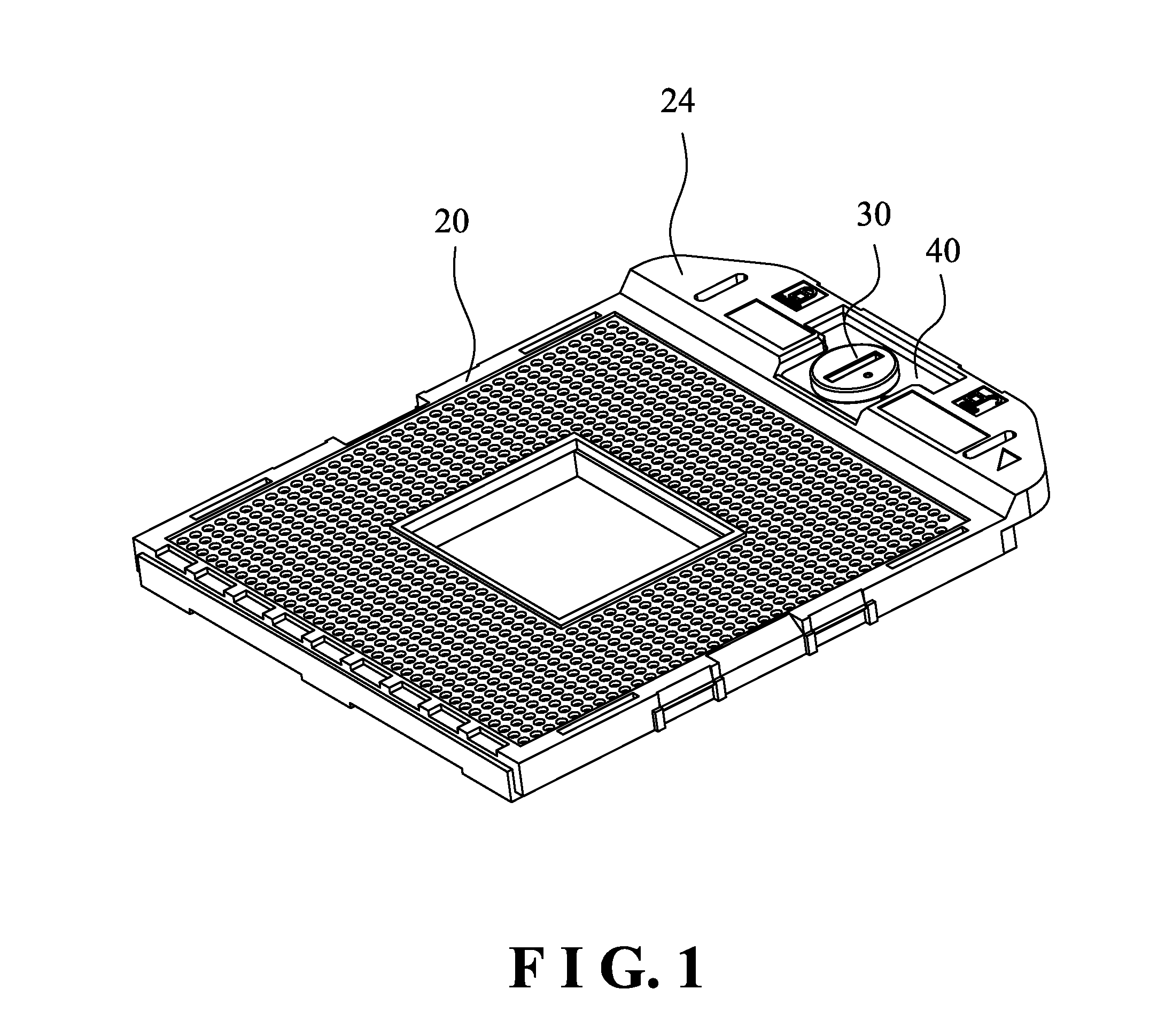
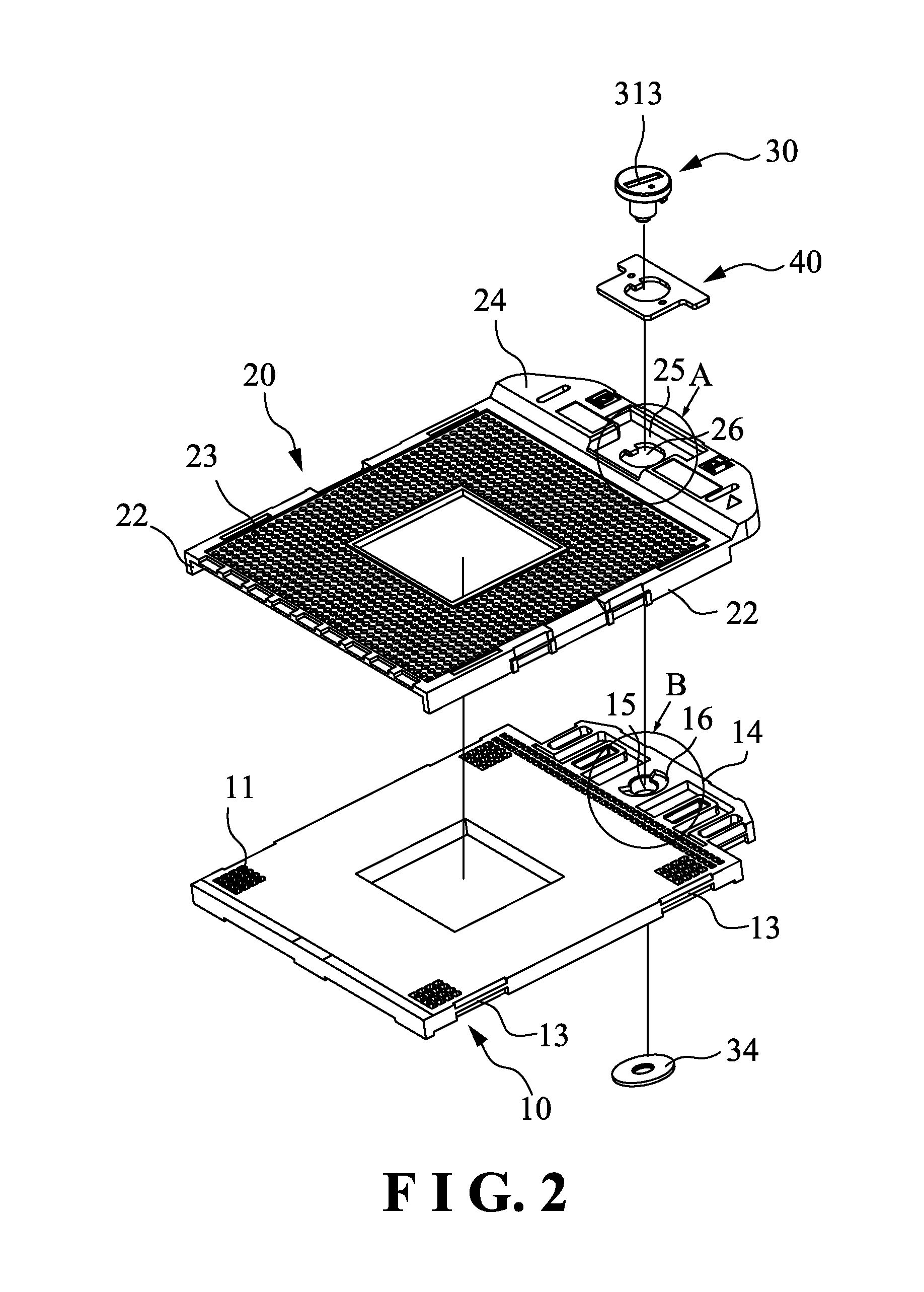
[0039]As shown in FIG. 1 through FIG. 10, the electric connector according to a first embodiment of the present invention comprises an insulation base 10, a cover 20 which is slidably connected to the base 10, and an eccentric driving cam 30 which is connected to the insulation base 10 and the cover 20.

[0040]In this embodiment, the front, rear, left, right directions described hereinafter are based on FIG. 1. The detailed structure of the electric connector is as follows.

[0041]As shown in FIG. 2 and FIG. 7, the insulation base 10 is in a square flat shape and used to connect a circuit board. The insulation base 10 has a plurality of lower receiving holes 11 thereon to receive socket terminals. The insulation base 10 comprises a plurality of engaging blocks 13 at two sides thereof. The insulation base 10 comprises a base platform 14 extending from a fr...


PUM


Abstract

An electric connector includes an insulation base, a cover which is slidably connected to the base and an eccentric driving cam which is connected to the insulation base and the cover. The insulation base has a first limit surface. The cover has a second limit surface. The eccentric driving cam includes a first stop surface and a second stop surface. The first stop surface is stopped by the first limit surface and the second stop surface is stopped by the second limit surface, providing a dual-stop effect.

Description

BACKGROUND OF THE INVENTION[0001]1. Field of the Invention[0002]The present invention relates to an electric connector to connect a central processing unit and a motherboard, and more particularly to an electric connector driving by a cam.[0003]2. Description of the Prior Art[0004]A conventional electric connector to connect a central processing unit and a motherboard comprises an insulation base and a cover. The cover has a plurality of upper receiving holes, and the insulation base has a plurality of lower receiving holes corresponding to the upper receiving holes. Each lower receiving hole is provided with a socket terminal. A driving device is connected to the cover and the insulation base and used to open or close the electric connector. When the electric connector is in a disconnection state, the pins of the CPU chip module are not contact with the corresponding socket terminals. After that, the driving device is operated to move the cover toward one side of the insulation bas...

Claims


Application Information

Patent Timeline
Patent Type & Authority Patents(United States)
IPC IPC(8): H01R4/50
CPCH01R13/193H05K7/1007
Inventor TSAI, CHIA YEN
Owner SUYING ELECTRCNICS (DONG GUAN) CO LTD
Why Eureka
Try Eureka