Dual-clutch group transmission and method for actuating a dual-clutch group transmission

a transmission and clutch group technology, applied in mechanical equipment, transportation and packaging, gear shifting, etc., can solve the problems of reducing the efficiency of the transmission, the process of the range group itself being as a rule not traction force-supported, and the power-shifting of not all the gears. to achieve the effect of saving weight and shortening the axial length of the transmission

Active Publication Date: 2013-04-16
ZF FRIEDRICHSHAFEN AG
View PDF14 Cites 7 Cited by
  • Summary
  • Abstract
  • Description
  • Claims
  • Application Information

AI Technical Summary

Benefits of technology

[0019]For example, in an upshift from a direct gear in the lower gear range, i.e. from the highest gear of the lower gear range, to the next higher gear, i.e. to the lowest gear of the upper gear range, this enables a power-shifted and comfortable gearshift with a shift of the range group. Thus, in such an upshift, while the direct gear in the lower gear range is engaged before the shift of the range group by directly connecting the inner transmission input shaft to the main transmission shaft and closing the associated input clutch, the hollow shaft according to the invention on the main transmission shaft is engaged with the planetary carrier and a gearwheel or a loose wheel, preferably of the 1st gear. Thereby, the outer transmission input shaft is functionally connected to the transmission output shaft. In that case a shifting element for shifting the range group, with which the force flow is switched between a coupling of the ring gear to a housing component for the geared lower gear range or a coupling of the ring gear to the planetary carrier for the upper gear range in which the planetary transmission is blocked, can be shifted to neutral. For the subsequent power-shifted gearshift it is only necessary to open the closed input clutch and close the other input clutch in an overlapped manner. Thus, the shift by way of the range group is no longer perceived by the driver as disturbing, which therefore increases the driving comfort.
[0022]This transmission structure provides a total of fourteen forward gears with power-shifting of the range group, such that the seventh gear can be engaged as a direct gear in the lower gear range and the fourteenth gear as a direct gear in the upper gear range, and gears eight, nine and ten can be engaged by way of the planetary carrier. The fourteen-gear transmission enables a relatively large overall spread and particularly efficient driving operation in the commercial vehicle sector.
[0025]The second transmission structure has a total of eight forward gears with power-shifting of the range group, wherein the fourth gear can be engaged as a direct gear in the lower range group and the eighth gear as a direct gear in the upper gear range, and gears five, six and seven can be engaged by way of the planetary carrier. Compared with the transmission with fourteen gears, one shifting element can be saved so that an even shorter axial length of the transmission and a saving of weight can be achieved. In a transmission having the second transmission structure, all the gears can be power-shifted.

Problems solved by technology

However, in common with all manual or automated variable-speed transmissions they are inherently associated with an interruption of the traction force.
However, in transmissions designed in such manner not all the gears can necessarily be power-shifted.
However, the shifting process of the range group itself is as a rule not traction-force-supported.
Since in addition the shifting process lasts a comparatively long time, this is regularly sensed by the driver and perceived as annoying.
However, a shift of the downstream range group between a lower gear range stepped down by the planetary transmission and an upper gear range not stepped down due to blocking of the planetary transmission, is not traction-force-supported.
If in the usual way the main transmission shaft is connected at its output-side end directly to a sun gear of the range group but only indirectly to a transmission output shaft at the output of the range group, then during a shift of the range group in which the force flow changes, for example, between a coupling of a ring gear to a housing and a coupling of the ring gear to a transmission output shaft connected to a planetary carrier, the intermediate gear cannot provide any traction-force support.
However, the range group itself can still not be power-shifted.
Accordingly, in transmission designs that do not provide for any intermediate gear engagement, the range shift is again not traction-force-supported.
Furthermore, the hollow shaft that extends as far as the sun gear is relatively long, so the mounting of the very long main transmission shaft passing through the hollow shaft and extending from the starting clutch to the transmission output, rather falls short of optimum.

Method used


Image

  • Dual-clutch group transmission and method for actuating a dual-clutch group transmission
  • Dual-clutch group transmission and method for actuating a dual-clutch group transmission
  • Dual-clutch group transmission and method for actuating a dual-clutch group transmission

Examples


Embodiment Construction

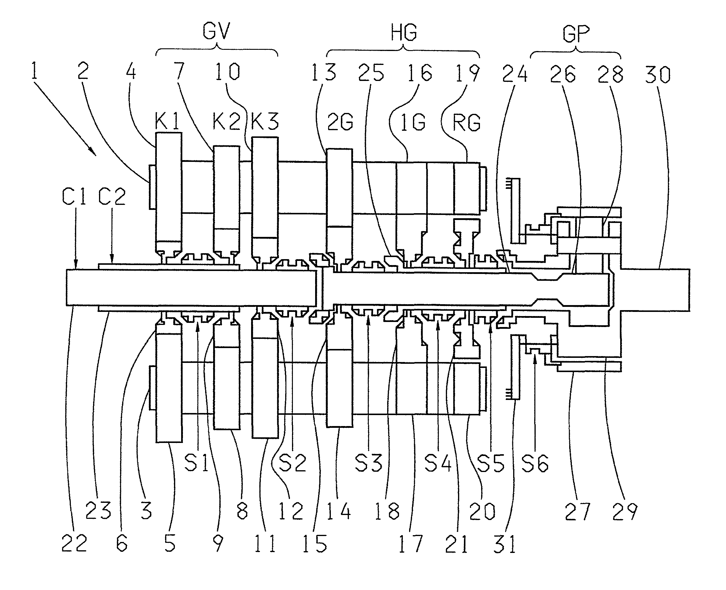
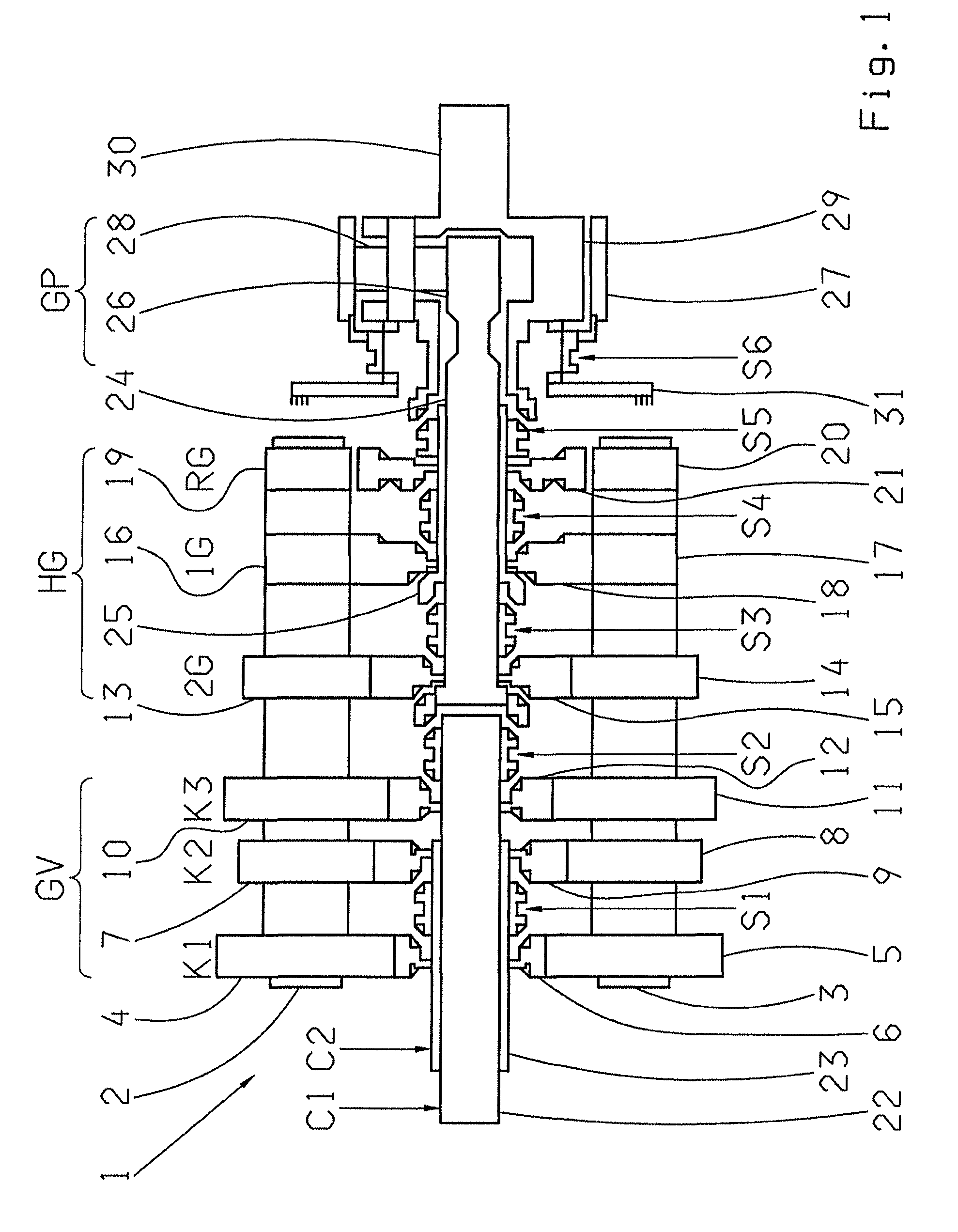
[0031]Accordingly, FIG. 1 is a schematic representation of a first transmission structure 1 of a dual-clutch group transmission as can be provided, for example, for a truck. The transmission structure 1 comprises three transmission groups GV, HG, GP. A splitter group GV on the input side with three input constants K1, K2, K3, a main group HG with a first gear 1G, a second gear 2G and a reverse gear RG, and a range group GP with a lower gear range GPL and an upper gear range GPS are arranged axially one after another.

[0032]The splitter group GV and the main group HG are formed as countershaft transmissions with two common, axis-parallel countershafts 2, 3. The gear constants K1, K2, K3 and the gears 2G, 1G, RG comprise gearsets, each with two fixed wheels 4, 5; 7, 8; 10, 11; 13, 14; 16, 17; 19, 20, which are arranged on the countershafts 2, 3 and each of which engages with a loose wheel 6, 9, 12, 15, 18 and 21 respectively, these being mounted to rotate and engaging with the associat...


PUM


Abstract

A dual-clutch group transmission having splitter, main and range groups. The range group is a planetary transmission with a ring gear, a sun gear and planetary gears that are supported by a carrier. Inner and outer transmission input shafts are connected to a respective first and second clutch. A main transmission shaft and shifting elements for engaging gears or forming frictional connections. Power-gearshifts, involving a shift of the range group, are enabled because the inner input shaft can be directly connected, via a shift element, to the main shaft. A hollow shaft extends coaxially over the main shaft and supports a loose wheel of a forward gear of the main group. The wheel can be rotationally fixed, via a shift element, to the hollow shaft which can be connected to the main shaft and the carrier by respective shifting elements.

Description

[0001]This application is a National Stage completion of PCT / EP2011 / 053086 filed Mar. 2, 2011, which claims priority from German patent application serial no. 10 2010 003 924.1 filed Apr. 13, 2010.FIELD OF THE INVENTION[0002]The invention concerns a dual clutch group transmission and a method for actuating a dual clutch group transmission.BACKGROUND OF THE INVENTION[0003]Group transmissions and dual clutch transmissions are known transmission types. Moreover, group transmissions that comprise a dual clutch are also known.[0004]Group, or multi-group transmissions have the advantages that by combining two or three transmission groups they provide a large number of gears, they operate efficiently, and with regard to their number of gears they can be produced in a structurally compact form. However, in common with all manual or automated variable-speed transmissions they are inherently associated with an interruption of the traction force. In contrast, dual clutch transmissions have the...

Claims


Application Information

Patent Timeline
Patent Type & Authority Patents(United States)
IPC IPC(8): F16H48/06
CPCF16H3/006F16H3/095F16H37/046F16H37/043Y10T74/19228F16H2003/0818F16H2200/0065Y10T74/19233
Inventor RENNER, STEFAN
Owner ZF FRIEDRICHSHAFEN AG
Why Eureka
Try Eureka