
Wireless railroad monitoring

a wireless, railroad technology, applied in the direction of vehicle position/course/altitude control, process and machine control, instruments, etc., can solve the problems of increasing installation and maintenance costs of such a system, and achieve the effect of flexible solutions, more efficient, and reliabl

Active Publication Date: 2013-04-16
INT ELECTRONICS MACHINES
View PDF11 Cites 38 Cited by
  • Summary
  • Abstract
  • Description
  • Claims
  • Application Information

AI Technical Summary

Benefits of technology

The patent proposes a solution for monitoring and controlling rail operations using wireless sensors that do not require physical power or communication connections. The sensors are powered by the rail operations and can transmit data wirelessly. The solution provides a more efficient, reliable, and flexible way of monitoring and maintaining rail infrastructure. This is achieved by deploying sensor nodes that acquire data on various properties of the railroad environment and generate sufficient power to operate the sensor node without access to any additional power sources. The sensor nodes can be deployed as part of a group of sensor nodes providing data for use by the railroad system. Overall, this invention offers an innovative solution for monitoring and controlling rail operations.

Problems solved by technology

Such wiring substantially increases the installation and maintenance costs for such a system.

Method used


Image

  • Wireless railroad monitoring
  • Wireless railroad monitoring
  • Wireless railroad monitoring

Examples


Embodiment Construction

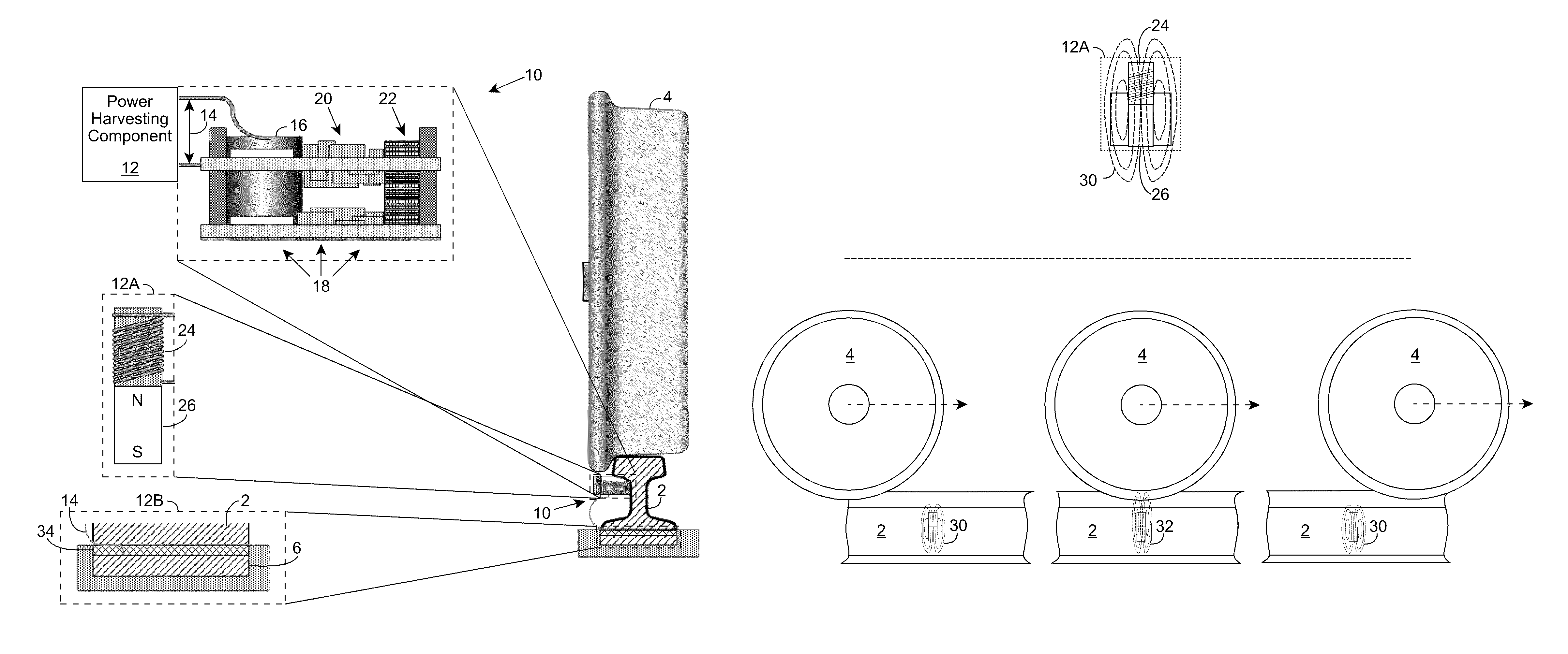
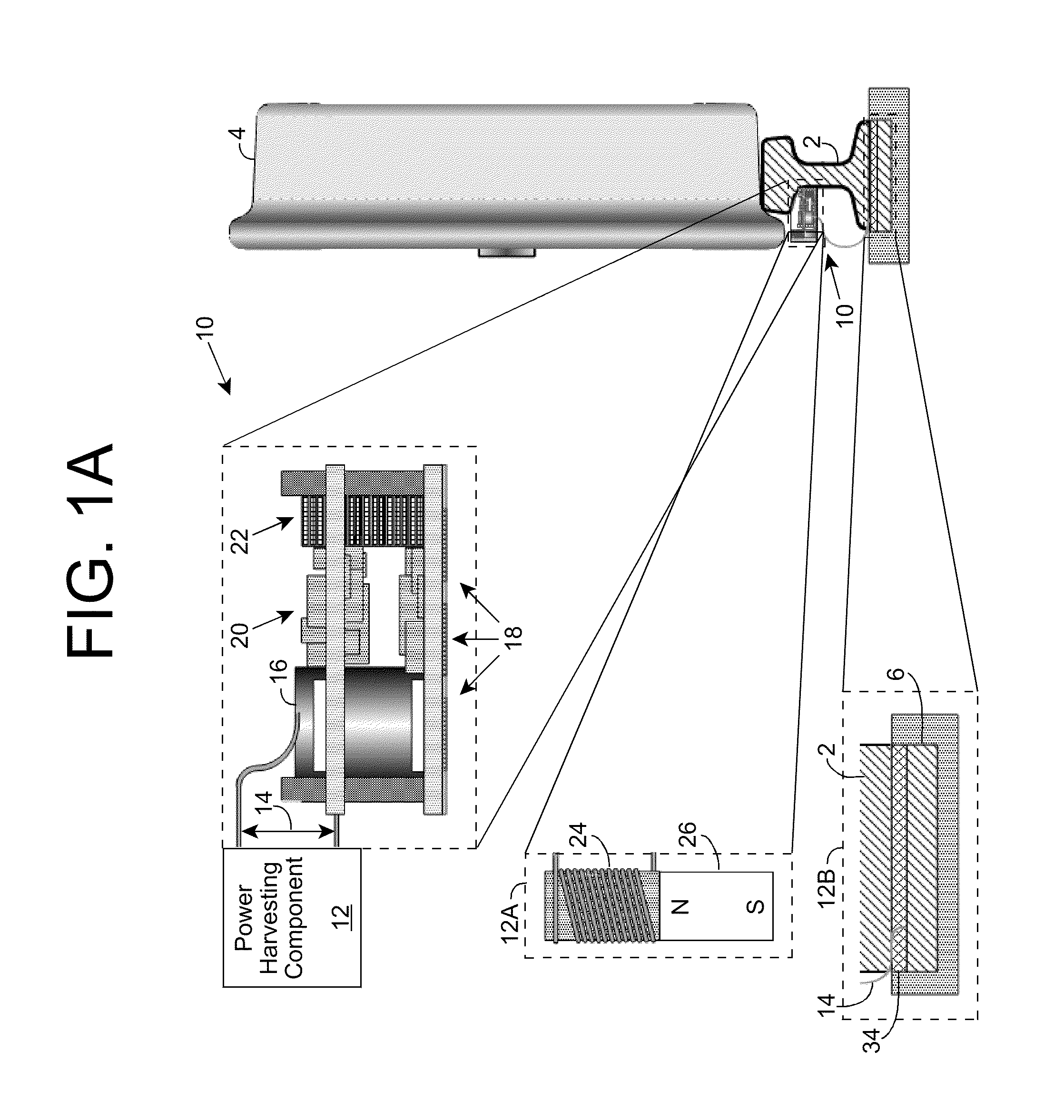
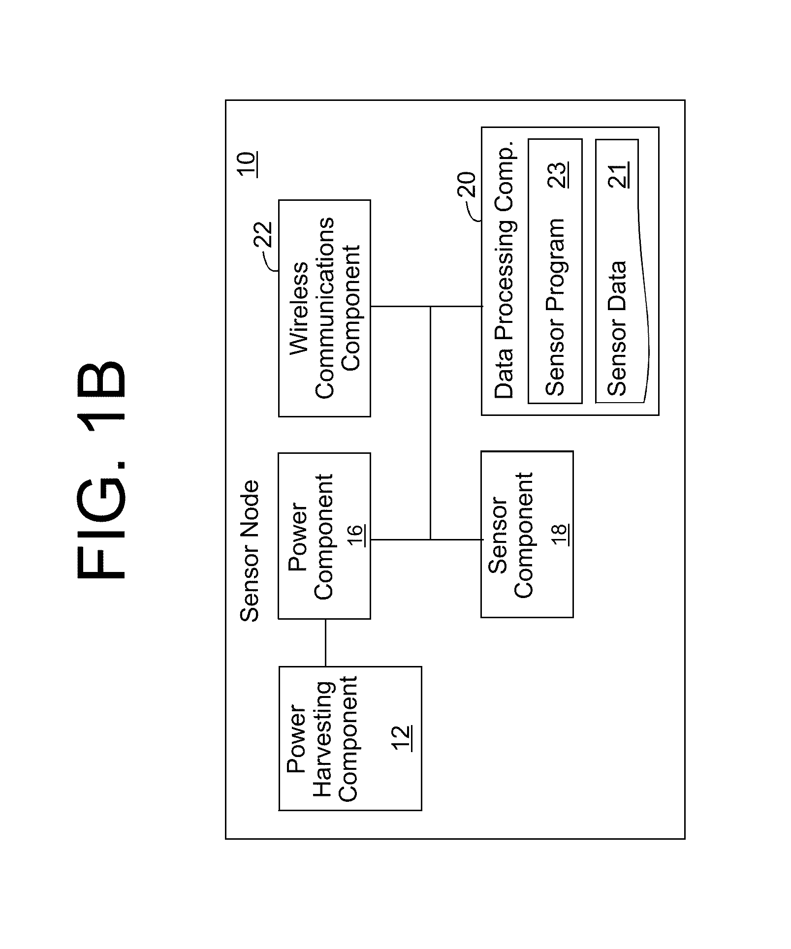
[0017]As indicated above, aspects of the invention provide a sensor node configured to acquire sensor data on one or more properties of a railroad environment, wirelessly transmit data related to the property(ies), and generate sufficient power to operate the sensor node without access to any additional power sources. The sensor node can be deployed as part of a group of sensor nodes, which provide data for use by a railroad system in monitoring and / or controlling the railroad environment. In this manner, various properties of the railroad environment can be monitored without requiring significant wiring to the various sensor nodes. As used herein, unless otherwise noted, the term “set” means one or more (i.e., at least one) and the phrase “any solution” means any now known or later developed solution.

[0018]Turning to the drawings, FIGS. 1A and 1B show an illustrative wireless sensor node 10 according to an embodiment. As illustrated, some or all of sensor node 10 can be attached to...


PUM


Abstract

A sensor node configured to acquire sensor data on one or more properties of a railroad environment, wirelessly transmit data related to the property(ies), and generate sufficient power to operate the sensor node without access to any additional power sources is provided. The sensor node can be deployed as part of a group of sensor nodes, which provide data for use by a railroad system in monitoring and / or controlling the railroad environment. In this manner, various properties of the railroad environment can be monitored without requiring significant wiring to the various sensor nodes.

Description

REFERENCE TO PRIOR APPLICATIONS[0001]The current application claims the benefit of U.S. Provisional Application No. 61 / 129,487, titled “Self-powered wireless railroad infrastructure sensor network,” which was filed on 30 Jun. 2008, and which is hereby incorporated by reference. Aspects of the invention are related to U.S. Utility patent application Ser. No. 12 / 469,167, titled “Sensor System,” which was filed on May 20, 2009, and which is hereby incorporated by reference.TECHNICAL FIELD[0002]The disclosure relates generally to monitoring railroad operations, and more particularly, to a solution that includes independent, wireless sensor nodes configured to monitor one or more aspects of the railroad operations.BACKGROUND ART[0003]A wide variety of sensors are used in railroad settings. These sensors and illustrative applications include: wheel detectors, which are often used in railway operation to monitor train traffic; accelerometers, which can be used to detect impacts of flat whe...

Claims


Application Information

Patent Timeline
Patent Type & Authority Patents(United States)
IPC IPC(8): G06F7/00
CPCB61L1/165B61L1/168B61L1/169B61L27/0088B61L27/0094H02K35/02B61L27/57B61L27/53
Inventor MIAN, ZAHID F.
Owner INT ELECTRONICS MACHINES
Learn More