Eureka AIR delivers breakthrough ideas for toughest innovation challenges, trusted by R&D personnel around the world.

Intake manifold

a technology of intake manifold and intake manifold, which is applied in the direction of machines/engines, combustion air/fuel air treatment, and feed systems, etc., can solve the problems of reducing the combustion efficiency of the engine, affecting the intake performance, and generating a lot of turbulence about each inlet port, so as to improve the intake performance and reduce weigh

Inactive Publication Date: 2013-04-23
TOYOTA BOSHOKU KK +1
View PDF10 Cites 2 Cited by
  • Summary
  • Abstract
  • Description
  • Claims
  • Application Information

AI Technical Summary

Benefits of technology

[0008]The present invention was made for solving the above problems in the prior art. Accordingly, it is an objective of the present invention to provide an intake manifold that improves the intake performance and has a reduced weight.

Problems solved by technology

Thus, when air is drawn into the inlet ports, a great turbulence is likely to be generated about each inlet port.
Such turbulence disturbs smooth intake of air, possibly deteriorates the intake performance, and, as a result, lowers the combustion efficiency of the engine.
This is likely to generate a great turbulence between adjacent inlet ports, and particularly lowers the intake performance of the inlet ports on the downstream side.
As a result, the amount of air drawn into the inlet ports becomes uneven.
This not only lowers the combustion efficiency, but also generates irregular vibration as the engine operates.

Method used


Image

  • Intake manifold
  • Intake manifold
  • Intake manifold

Examples


Embodiment Construction

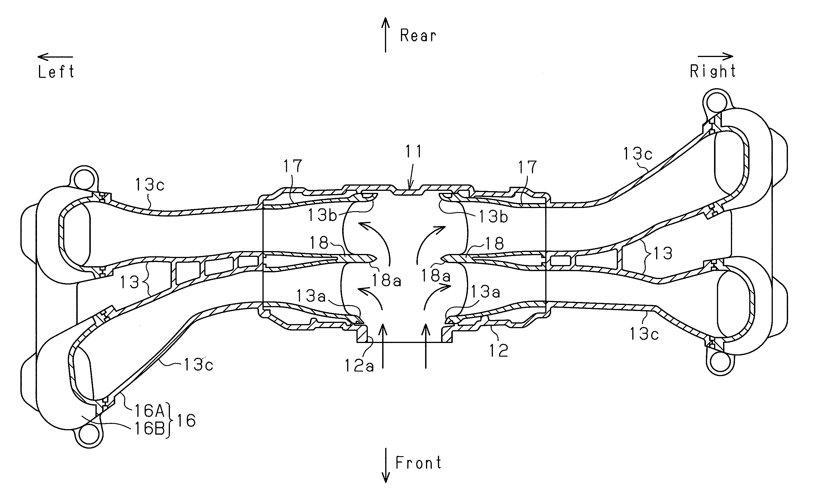
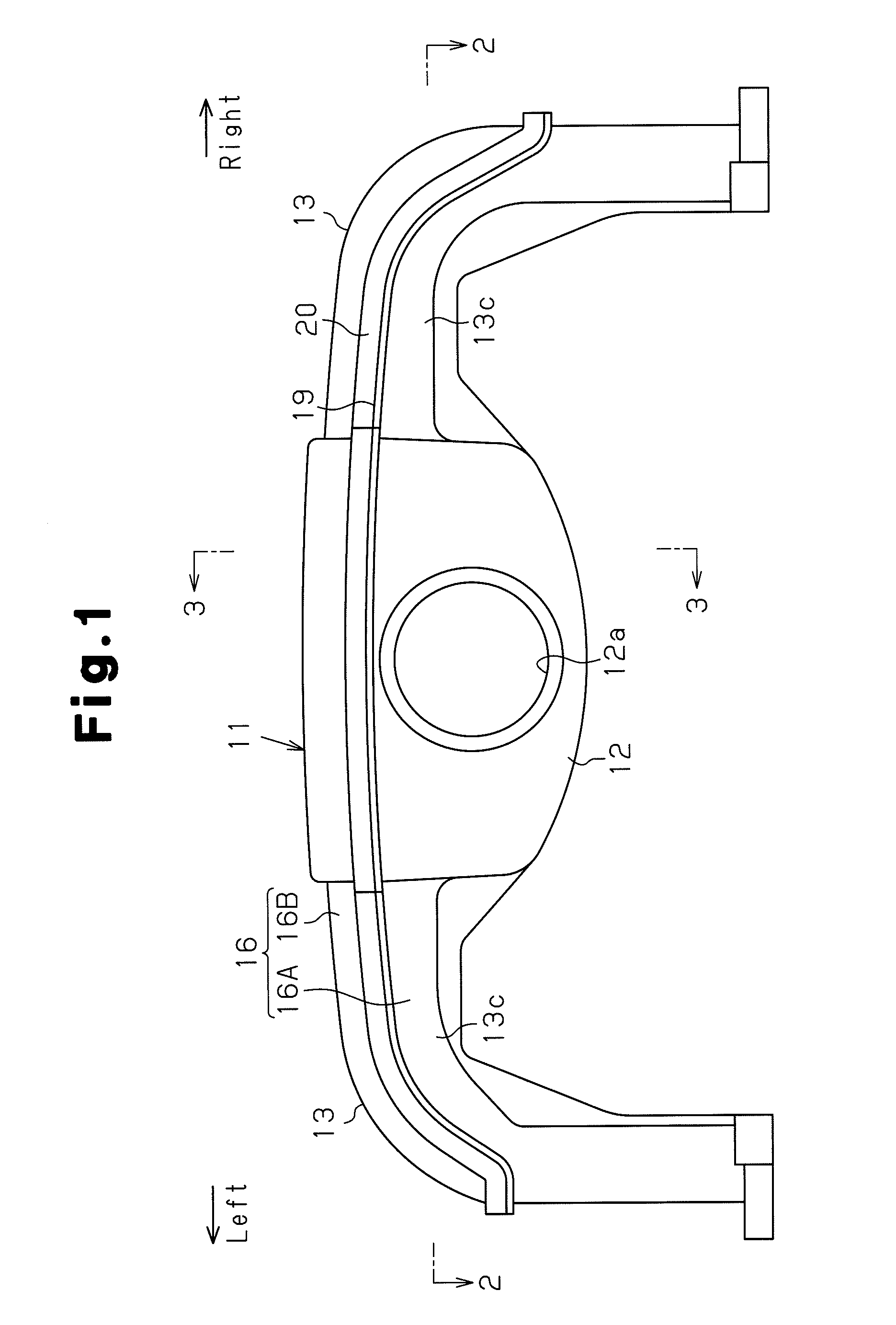
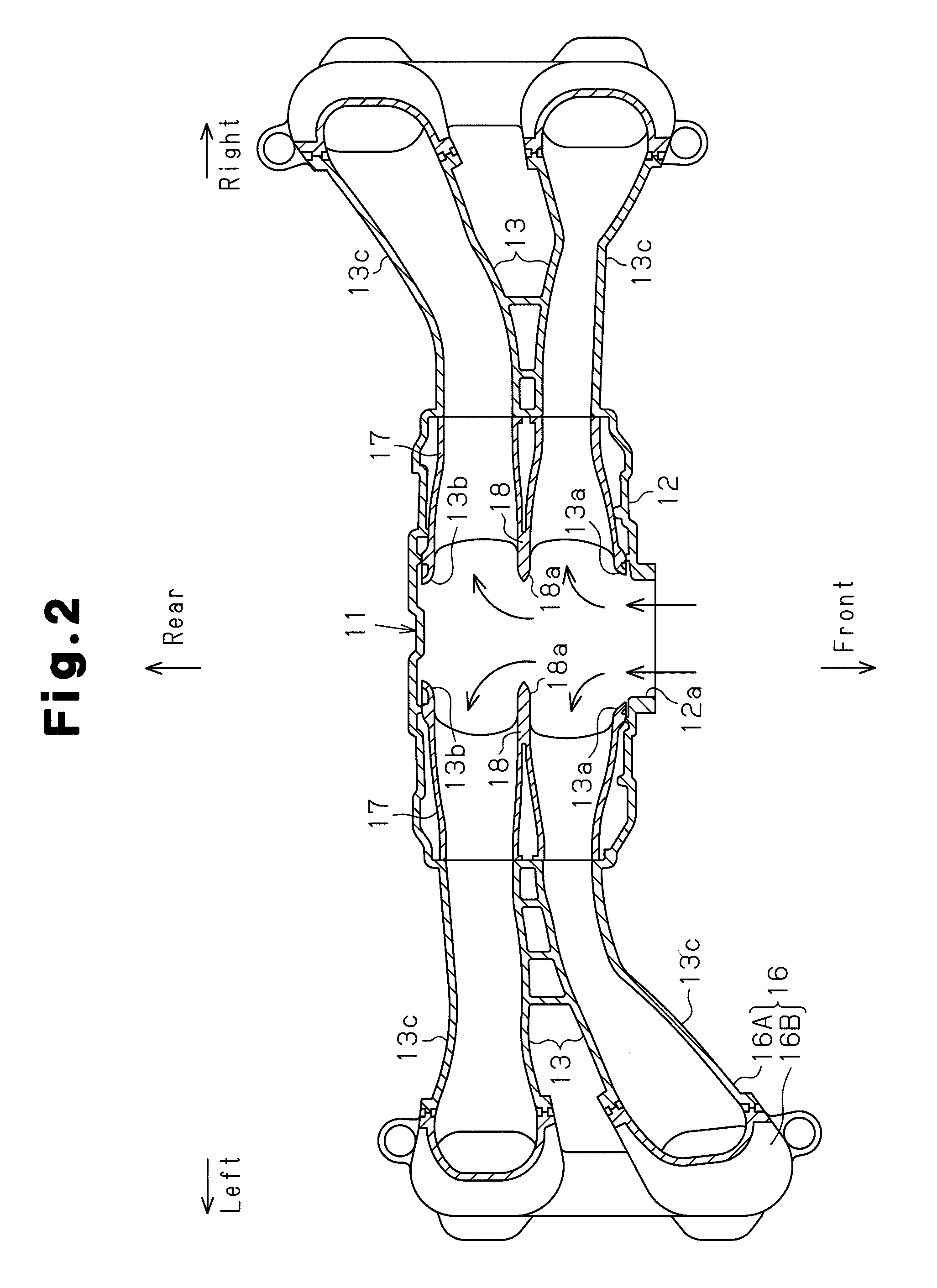
[0018]Hereinafter, an intake manifold 11 according to one embodiment of the present invention will now be described with reference to FIGS. 1 to 6. The intake manifold 11 is mounted in a horizontally-opposed four-cylinder engine. In this description, the left-right direction in FIG. 1 is defined as left-right direction of the intake manifold 11, and a direction perpendicular to the sheet of FIG. 1 is defined as the front-rear direction of the intake manifold 11.

[0019]With reference to FIGS. 1 to 3, the intake manifold 11 of the present embodiment is made of a heat resistant synthetic resin (for example, polyamide resin), and includes a surge tank 12 and pairs of intake pipes 13 provided on the left and right sides of the surge tank 12. The intake pipes 13 each correspond to one of the combustion chambers provided on both sides of the horizontal-opposed engine. Each pair of intake pipes 13 is formed by main bodies 13c and an inlet pipe member 17, which is formed separately from the m...


PUM


Abstract

The present invention provides an intake manifold that improves the intake performance and has a reduced weight. The intake manifold includes a surge tank and intake pipes. Each intake pipe has an inlet port that is connected to the surge tank. The inlet ports are arranged along a flow direction of air drawn into the surge tank from the opening of the surge tank, and project into the surge tank along direction that intersects the flow direction. Each adjacent pair of the inlet ports are separated only by a single common pipe wall.

Description

BACKGROUND OF THE INVENTION[0001]The present invention relates to an intake manifold in the intake system of an automobile engine.[0002]Known types of such intake manifolds include the ones disclosed, for example, in Japanese Laid-Open Patent Publication Nos. 9-177624 and 2008-184939.[0003]The intake manifold disclosed in Japanese Laid-Open Patent Publication No. 9-177624 includes a surge tank and a plurality of intake pipes each having an inlet port. The inlet ports of the intake pipes are connected to and protrude into the surge tank. The inlet ports extend in a direction of air flow from the opening of the surge tank, and are arranged along a direction perpendicular to the air flow direction.[0004]The intake manifold disclosed in Japanese Laid-Open Patent Publication No. 2008-184939 also includes a surge tank and a plurality of intake pipes each having an inlet port. The inlet ports of the intake pipes are connected to and protrude into the surge tank. These inlet ports are provi...

Claims


Application Information

Patent Timeline
Patent Type & Authority Patents(United States)
IPC IPC(8): F02M35/10
CPCF02M35/10039F02M35/10354F02M35/116
Inventor TAKAKUWA, MINORUINABA, HIDEKIIZUMI, KEITA
Owner TOYOTA BOSHOKU KK
Why Eureka
Eureka Blog
Learn More