
Ventilating air intake arrangement

a technology of air intake and air flow rate, which is applied in the direction of mechanical equipment, machines/engines, transportation and packaging, etc., can solve the problems of vapors to be expelled, too much air or air flow rate exiting the channel of the arrangement towards the zone to be ventilated, and too much cooling of devices

Inactive Publication Date: 2013-04-23
AIRBUS OPERATIONS (SAS)
View PDF13 Cites 5 Cited by
  • Summary
  • Abstract
  • Description
  • Claims
  • Application Information

AI Technical Summary

Benefits of technology

The present invention is about an air intake arrangement that can be used in vehicles like airplanes. Its design helps to ventilate closed and sensitive zones, while optimizing the air flow based on the airplane's flight phases. The arrangement includes a controllable fluid control that automatically inflates the membrane based on the total pressure of the fluid. This results in a simpler and more efficient system for ventilating airplanes.

Problems solved by technology

However, the devices to be cooled and the vapors to be expelled are not ventilated optimally by the known air intake arrangements.
In practice, in these arrangements, while the outside air entering upstream through the air vent into the channel with predetermined cross section of the arrangement and exiting downstream of the latter is sufficient to correctly ventilate the devices when the aircraft is in the taxiing phase, in a take-off phase or in a waiting phase, and therefore at low speed, on the other hand, when the aircraft is in cruising flight phase at maximum speed and altitude, the quantity of air or the air flow rate exiting from the channel of the arrangement towards the zone to be ventilated is too great.
This means that the devices are cooled too much, all the more so since the temperature of the external air is very low at this cruising altitude, which can lead to malfunctions.
Measurements have, moreover, shown that, in this flight phase, the air circulating in the confined zone via the channel of the arrangement was renewed twice as much as necessary, such that the fadec, in particular, is cooled excessively, which can be prejudicial to its satisfactory operation.

Method used


Image

  • Ventilating air intake arrangement
  • Ventilating air intake arrangement
  • Ventilating air intake arrangement

Examples


Embodiment Construction

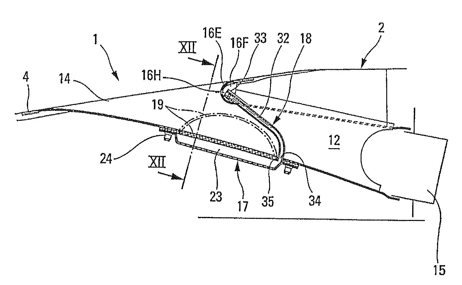
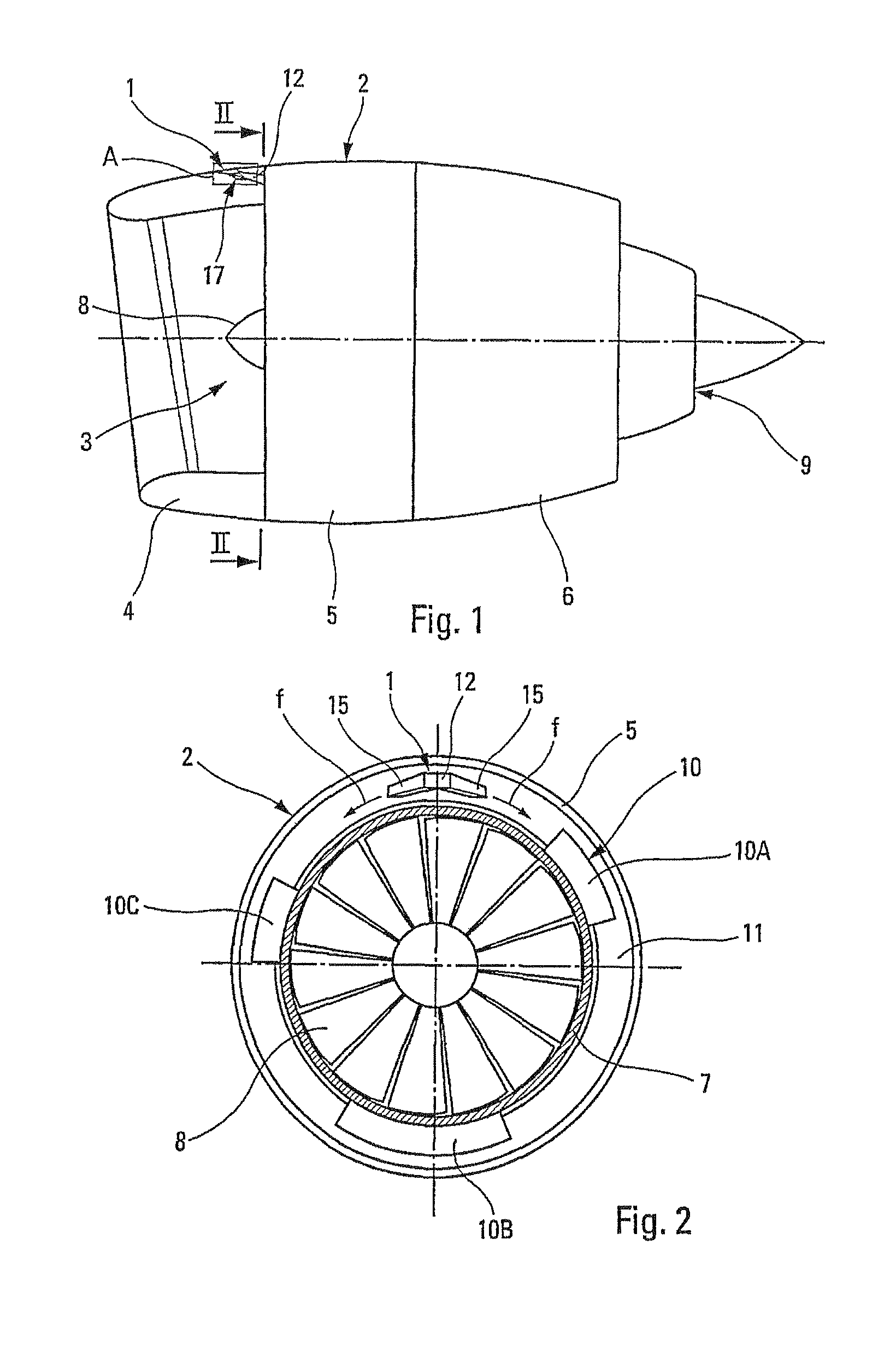
[0034]The ventilating air intake arrangement 1, according to the invention and delimited by a rectangle A in FIG. 1, is provided in a nacelle 2 of an airplane engine 3, such as a jet engine. As is diagrammatically shown in FIG. 1, the nacelle 2 usually comprises a front air intake part 4 for feeding air to the engine, a central part 5 surrounding the external casing 7 of the fan 8 and the compressors of the engine, and a rear part 6 surrounding the combustion chamber and the turbine, from which emerges the external casing of the nozzle 9 and its cone.

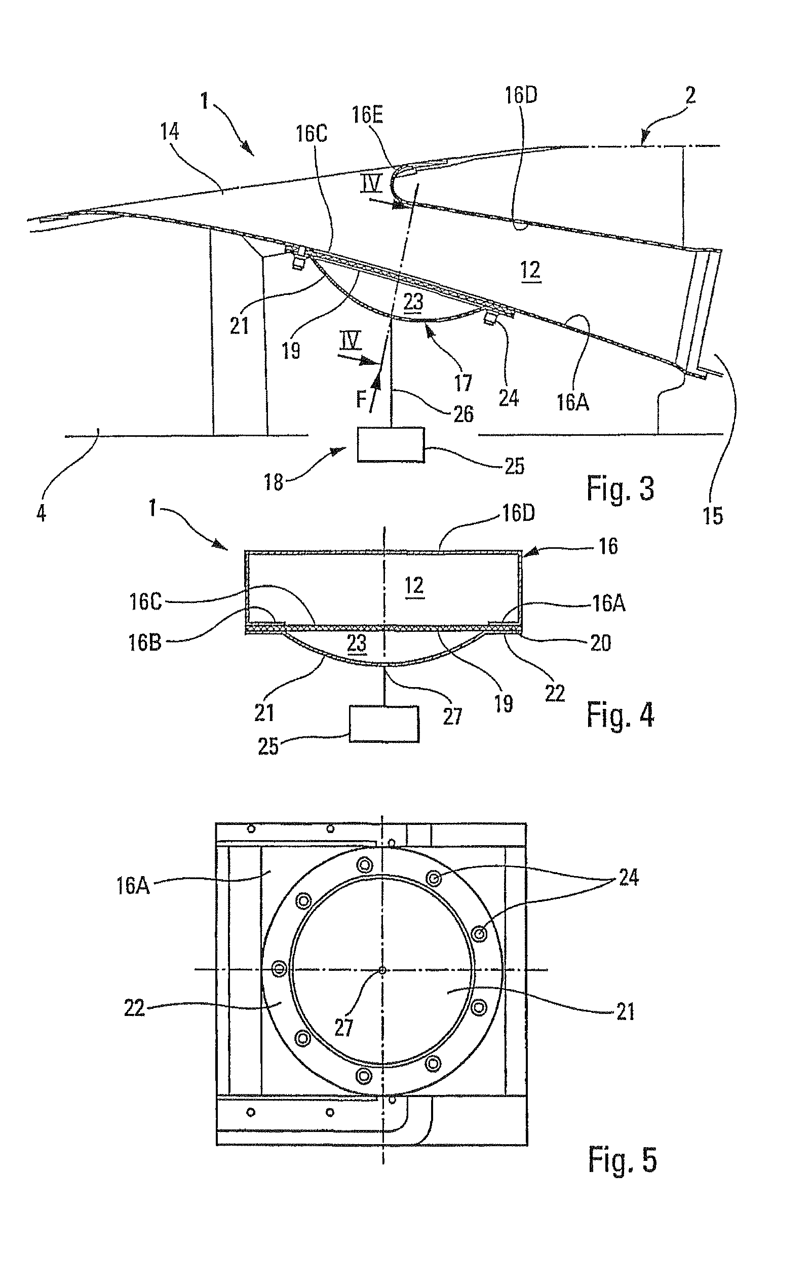
[0035]Various mechanical and / or electrical devices or items of equipment 10 are added to the external casing 7 of the fan and the compressors, namely in the confined annular space or zone 11 between the nacelle 2 and the external casing 7 of the engine 3. FIG. 2 symbolically shows some of the devices 10 located in this zone 11, namely the fadec 10A, the gearbox 10B and the engine oil tank 10C.

[0036]The renewal of the air in this confine...


PUM


Abstract

An aircraft ventilating air intake arrangement has an air passage channel and an air vent that ventilate a confined cone in an aircraft with fresh air entering the channel upstream and exiting the channel downstream towards the zone to be ventilated. A controllable blocking device enables the cross section of the channel to be varied with an elastically deformable membrane, under the action of fluid control, according to the speed and the altitude of the aircraft.

Description

FIELD OF THE INVENTION[0001]The present invention relates to a ventilating air intake arrangement comprising an air passage channel with an air vent, designed to ventilate at least one confined zone in a vehicle, for example an aircraft.BACKGROUND OF THE RELATED ART[0002]It is known that such ventilating air intake arrangements are widely used in the aeronautical field for air renewal purposes in a confined zone containing thermally sensitive equipment and / or hazardous ambient media, of the flammable or explosive type, for which it is necessary to ensure continuous ventilation of the zone in order to avoid any risk of the equipment malfunctioning or of a surrounding incident.[0003]Such is particularly the case with the numerous mechanical and / or electrical devices provided in the annular confined space or zone between the engine nacelle and the external fan casing and the compressors of an airplane jet engine. These devices, such as, for example, the fadec (full authority digital en...

Claims


Application Information

Patent Timeline
Patent Type & Authority Patents(United States)
IPC IPC(8): B64D13/02
CPCB64D33/08F02C7/042B64D2241/00
Inventor PORTE, ALAINPRAT, DAMIEN
Owner AIRBUS OPERATIONS (SAS)
Learn More