
Multidimensional evidence grids and system and methods for applying same

a multi-dimensional evidence and evidence system technology, applied in the field of multi-dimensional evidence grids and system and methods for applying same, can solve the problems of system malfunction or stoppage, inability to provide automated navigation, and inability to meet the requirements of the system,

Active Publication Date: 2013-04-23
SEEGRID CORPORATION
View PDF7 Cites 31 Cited by
  • Summary
  • Abstract
  • Description
  • Claims
  • Application Information

AI Technical Summary

Benefits of technology

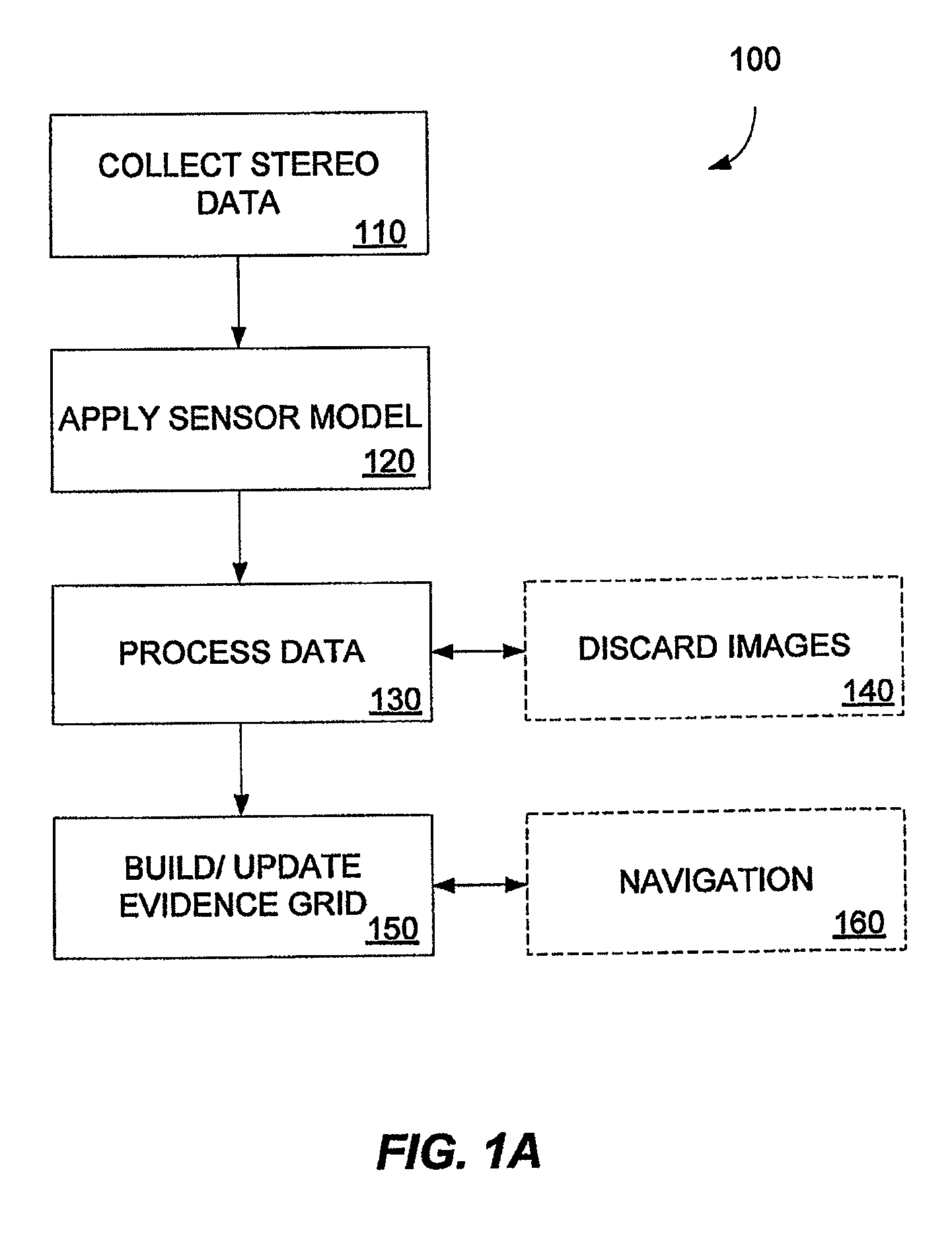
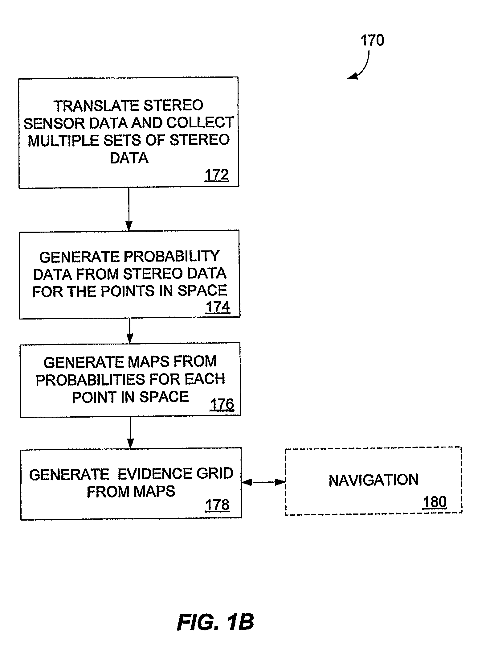
The present invention provides a navigation system and a mapping system for use with a mobile unit. The navigation system uses range sensors and an evidence grid to direct the mobile unit through the environment. The system also uses adjustable parameters to compensate for the inaccuracies of the range sensors. The mapping system uses the range sensors and adjustable parameters to create a map of the environment. The invention also provides a method for generating a pixel mapping table to correct images for distortions related to the range sensors. The technical effects include improved accuracy and efficiency in navigation and mapping.

Problems solved by technology

Previous attempts at providing automated navigation have been limited in their flexibility, and also in their success.
Breaks in the guide-path can lead to system malfunction or stoppage.
Blocking a line of sight path between a target and the vehicle's laser or a corresponding receiver can cause system malfunction or stoppage.
These systems are extremely susceptible to error build-up over time, which limits their accuracy.
Like the other systems, these types of systems are unable to respond to changes in the workplace.
Due to the sparsity of the data in 2-D evidence grids, they tend to be unreliable and impractical in real-world environments.
However, construction of such 3-D evidence grids has been computationally burdensome—to the point of having limited real-world application.
This can lead to unsatisfactory and potentially intolerable results when guesses are wrong or when the computational burden makes the system too slow for practical applications.

Method used


Image

  • Multidimensional evidence grids and system and methods for applying same
  • Multidimensional evidence grids and system and methods for applying same
  • Multidimensional evidence grids and system and methods for applying same

Examples


embodiment of implementation details

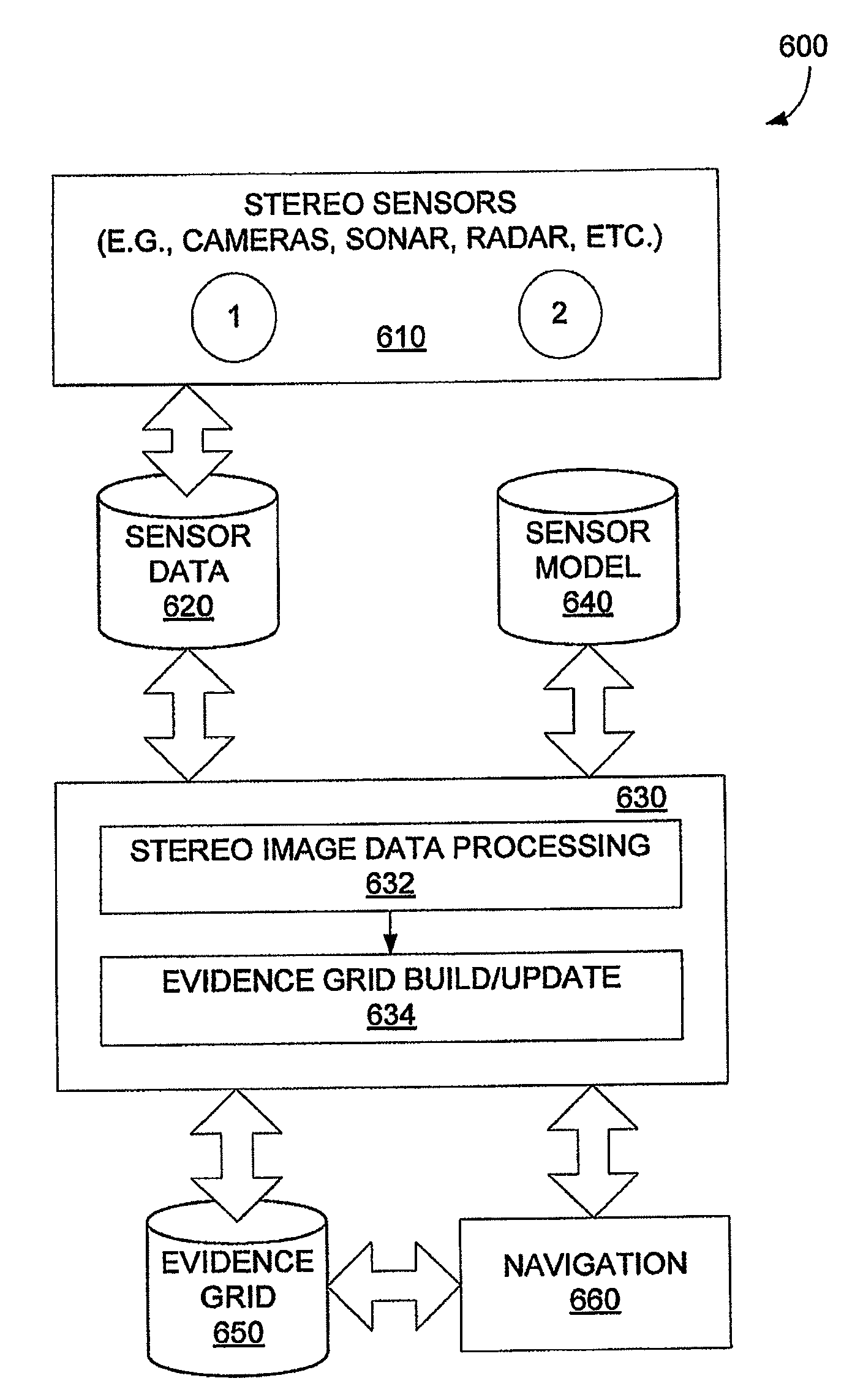
[0085]Below is described embodiments of possible implementation details of evidence grid building module 630 (or “grid engine”) of FIG. 6. These implementations can be viewed as alternative embodiments to that described above, or further detail expanding on the above described embodiments.

[0086]Grid engine stereoscopic vision, mapping and localization behavior is shaped by several dozen parameters. The parameters are incrementally adjusted by a learning process that attempts to optimize performance of the grid engine 634, as characterized by a numerical quantity. Trial settings of the parameters can be repeatedly tested against a body of calibrated test data. To optimize localization performance, the optimized quantity can be a combination of localization accuracy and run speed. Some of these learned parameters are explicitly described below. A full set of parameters, especially an optimized set, is referred to as the sensor model.

Camera Calibration / Image Rectification

[0087]Camera c...


PUM


Abstract

Mapping, localization, and navigation systems for use with a mobile unit are provided that use a sensor model with adjustable parameters. The system includes range sensors configured to collect range data and a data storage system having stored therein an evidence grid representing an environment and a sensor model comprising adjustable parameters representing inaccuracies of the range sensors. A grid engine adjusts the adjustable parameters based on received range data from the range sensors. A navigation module can direct the mobile unit though the environment using the evidence grid, received range data, and adjustable parameters. The grid engine can also locate the mobile unit within the environment by using the adjusted sensor model parameters to compare the received range data against the evidence grid.

Description

RELATED APPLICATIONS[0001]This application is a continuation-in-part application of co-pending non-provisional patent application Ser. No. 11 / 350,195, entitled Multidimensional Evidence Grids and System and Methods for Applying Same, filed Feb. 8, 2006, which claims the benefit of provisional application Ser. No. 60 / 650,904 filed on Feb. 8, 2005, both of which are incorporated herein by reference in their entirety.FIELD OF INTEREST[0002]The present inventive concepts relate to systems and methods for generating and utilizing multidimensional representations of an environment.BACKGROUND[0003]As an example, systems and methods for generating 2-dimensional (2-D) or 3-dimensional (3-D) representations of an environment can be useful in a variety of applications, such as in automated navigation systems and methods. For example, such automated systems and methods could be used to help guide a vehicle through the environment. As used herein, a vehicle can be any platform capable of transla...

Claims


Application Information

Patent Timeline
Patent Type & Authority Patents(United States)
IPC IPC(8): G06T17/00
CPCG05D1/0251G05D1/0274G05D1/0255G05D1/0257
Inventor MORAVEC, HANS
Owner SEEGRID CORPORATION
Learn More