Modular system for cladding exterior walls of a structure and insulating the structure walls

a technology of cladding and structure walls, applied in the field of static structures, can solve the problems of reducing conducting thermal energy through the wall structure, and degrading the effectiveness of insulation,

Active Publication Date: 2013-04-30
KNIGHT WALL SYST
View PDF52 Cites 31 Cited by
  • Summary
  • Abstract
  • Description
  • Claims
  • Application Information

AI Technical Summary

Benefits of technology

[0038]a further object to provide a modular system that minimizes thermal energy transfer from the exterior of a wall to the interior of a wall and from the interior of a wall to the exterior of a wall.
[0041]a further object to provide a modular system that prevents penetration and passage of moisture into the structure wall.
[0045]a further object to provide a modular system that decreases the cost of insulating a structure and increases the effectiveness of the insulation.
[0046]a further object to provide a modular system that allows a structure's exterior walls to be re-plumbed to vertical.
[0054]a further object to provide modular system that eliminates the need for massive foundations to support the weight of brick, stone and masonry cladding.
[0055]a further object to provide a modular system that reduces condensation within the wall assembly and effectively manages moisture within the wall assembly.

Problems solved by technology

One drawback to such wall framing methods is that such methods create thermal bridges in the structure's walls which decrease the effectiveness of insulation and conduct thermal energy through the wall structure from the inside to the outside, and from the outside to the inside depending upon the outside temperatures and the inside operating conditions.
Although insulation is provided between the wall studs, the studs themselves provide less insulative value and walls formed by such methods are not thermally efficient because thermal transfer occurs through the wall studs.
In warm weather months, the condensation usually forms on the outward facing surface of the insulation by warm air penetrating the wall from the outside and contacting the cooler outward facing surface of the insulation which can lead to moisture saturation of the insulation which degrades the effectiveness of the insulation.
Without proper design and engineering, attaching insulation directly to the exterior of a structure can be ineffective and can even be detrimental to the useful life of the wall assembly.
Another drawback to such construction methods is the limited number of options for cladding the exterior of a light-frame structure.
Although some variety of exterior claddings are available, such as lap board, metal siding, paneling and the like, such cladding is typically limited to light weight coverings that can be supported by hanger-type wall attachments.
Cladding exterior walls with heavy materials such as brick, stone and the like has previously been difficult because the weight of such coverings must be supported by the wall attachments.
Overcoming this difficulty leads to additional costs and expenses for larger foundations for vertical support, stronger beams for horizontal support and additional labor costs.
A further drawback to such construction methods is the limited ability to refurbish existing structures by changing the exterior.
Generally, when an existing structure is “re-clad” the options available are limited to replacing the existing cladding, or fastening a similar type of cladding over the top of the existing cladding.
Unfortunately, at times this is not feasible because the existing cladding is too deteriorated to allow stable attachment of the new cladding system.
Further, in some instances the vertical “plumbness” of an exterior wall might be so poor that it is not feasible or practical to attach a new exterior cladding to the existing structure.
Finally, attaching a new exterior cladding has the ability to alter the building's footprint sufficiently to cause property line set-back problems by extending the building's walls outwardly.
Our system allows the exterior of a structure to be clad in a material that has the appearance and texture of masonry, brick, stone and the like, but the cladding system does not have the weight of such construction and therefore the foundation and other underlying support structures of the building need not have the massiveness or therefore the cost and expense of support structures that would be necessary to support construction with such heavy materials.

Method used


Image

  • Modular system for cladding exterior walls of a structure and insulating the structure walls
  • Modular system for cladding exterior walls of a structure and insulating the structure walls
  • Modular system for cladding exterior walls of a structure and insulating the structure walls

Examples


Embodiment Construction

[0089]As used herein, the term “outer”, its derivatives and grammatical equivalents refers to that portion of our system that is proximate exterior of a structure. The term “inner”, its derivatives and grammatical equivalents refers to that portion of our, system that is proximate interior of the structure. The term “lower”, its derivatives and grammatical equivalents refers to that portion of our system that is vertically proximate foundation of the structure. The term “upper” its derivatives and grammatical equivalents refers to that portion of our system that is vertically distal from the foundation.

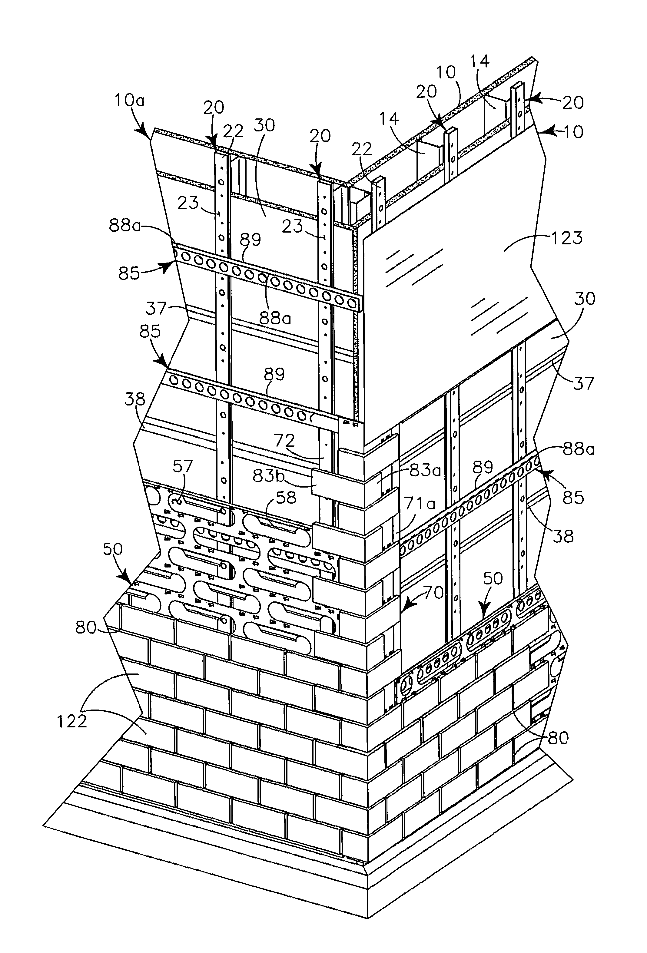
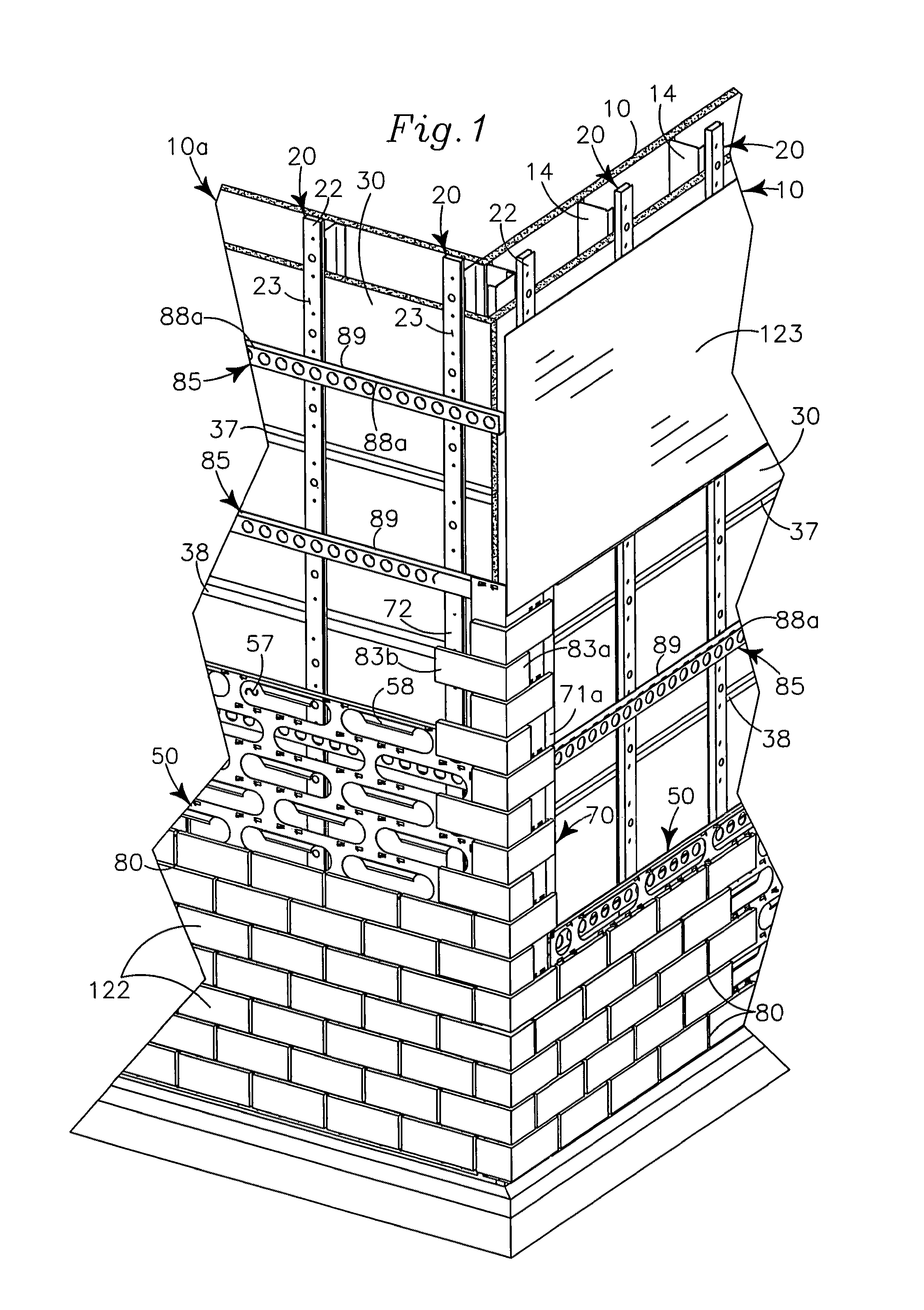
[0090]Our modular system for cladding exterior walls of a structure and insulating the structure walls generally provides vertical girders 20, 40, insulation panels 30, corner elements 70, U shaped hangers 85, wall panels 50 and exterior cladding 19.

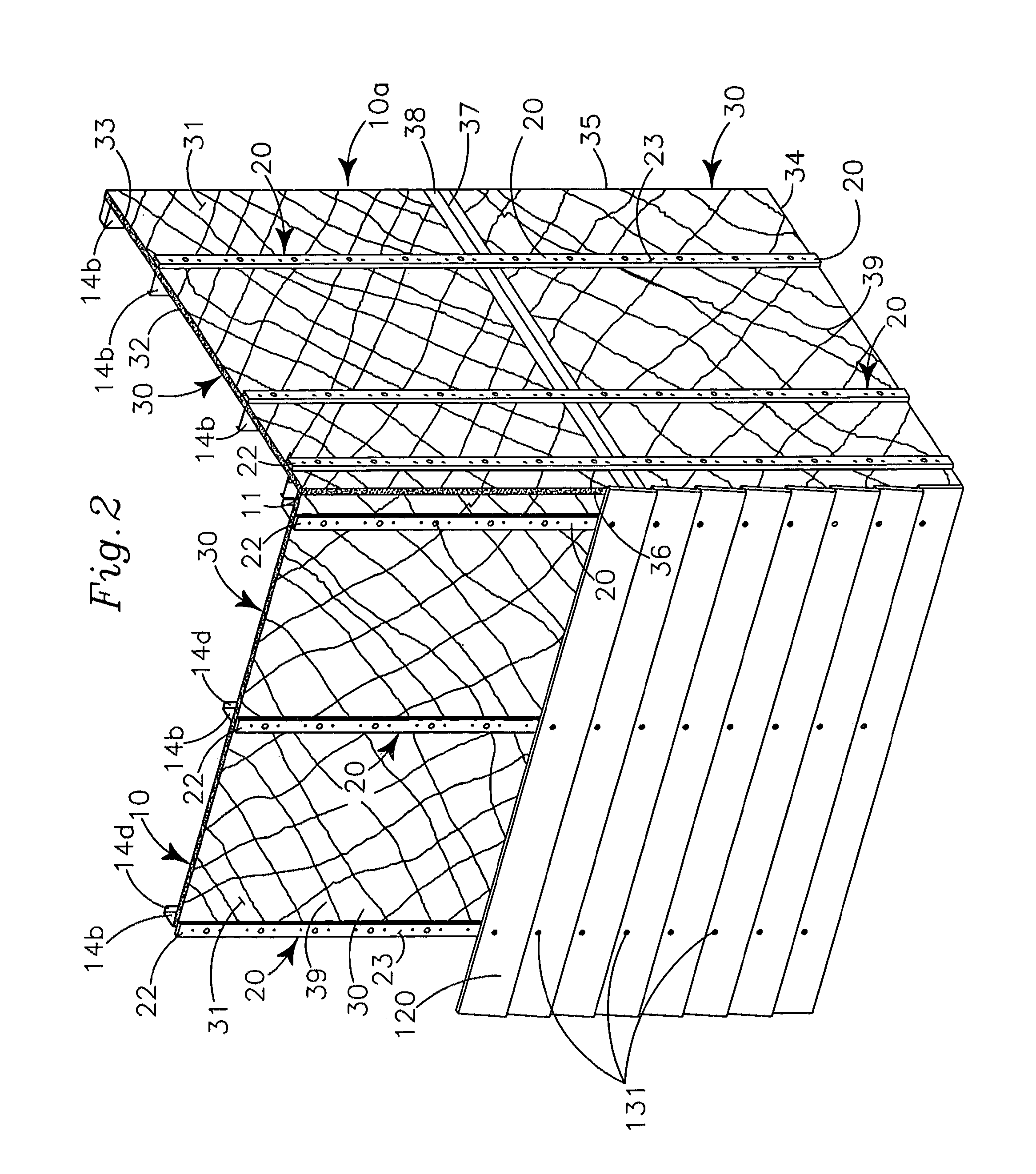
[0091]As shown in FIG. 2, a structure wall 10 is commonly formed of plural spaced apart vertical wall studs 14 that communicate between a...


PUM


Abstract

A modular system for cladding exterior walls of a structure and insulating the structure walls provides thermally isolated vertical girders secured to a structural wall. The thermally isolated vertical girders positionally maintain insulation adjacent the structure and provide a means for mounting exterior wall cladding to the structure. Planar wall panels carrying exterior wall cladding elements mount directly or indirectly to the vertical girders. Corner elements, carrying exterior corner cladding elements interconnect with the underlying system and visually appear to interconnect with adjacent edge portions of the planar wall panels.

Description

RELATED APPLICATIONS[0001]A U.S. Design Patent Application, Application No. 29 / 348,952 for a “J” Channel was previously filed on Feb. 25, 2010. The “J” Channel is one component of the modular system disclosed and claimed herein. The inventors of U.S. Design Patent Application No. 29 / 348,952 are co-inventors of the instant invention.BACKGROUND OF INVENTION[0002]1. Field of Invention[0003]This invention relates to static structures, and more particularly to a modular system for mounting and supporting thermal insulation and exterior cladding on a structure.[0004]2. Background and Description of Prior Art[0005]It is well known in the construction field to build exterior structure walls with plural spaced apart parallel vertical studs of wood or metal. The studs communicate, at a bottom end portion with a wall plate that is anchored to a lower support which may be a building foundation, and at an upper end portion with a ceiling plate that extends generally perpendicular to the studs an...

Claims


Application Information

Patent Timeline
Patent Type & Authority Patents(United States)
IPC IPC(8): E04B9/00
CPCE04B2/58E04F13/0862E04F13/12E04F13/14E04F13/0733E04B2001/2469E04B2001/405Y02B30/94Y02A30/00Y02B30/90E04B2002/565E04B2001/389
Inventor KNIGHT, DOUGLAS JAMESKNIGHT, DAVID ALLENKNIGHT, KENNETH LEESIMONSON, HARLEY W.SCHWARTZ, JOELCROASDALE, SCOTT
Owner KNIGHT WALL SYST
Why Eureka
Try Eureka