Directional heat exchanger

a heat exchanger and directional technology, applied in the direction of instruments, nanotechnology, active medium materials, etc., can solve the problems of limited carnot efficiency and many traditional heat transfer and temperature regulation devices, and achieve the effect of minimizing conductive and convective thermal energy transfer

Inactive Publication Date: 2005-03-17
PRACTICAL TECH
View PDF7 Cites 7 Cited by
  • Summary
  • Abstract
  • Description
  • Claims
  • Application Information

AI Technical Summary

Benefits of technology

[0011] Another technical advantage of particular embodiments of the present invention is a directional heat exchanger minimizing conductive and convective thermal energy transfer by placing the photonic band gap radiative emitter and the load absorber in a vacuum chamber, and / or placing the photonic band gap radiative emitter and load absorber in close proximity and selecting remaining gas molecules with a high Knusden number.
[0012] A further technical advantage of particular embodiments of the present invention is a photonic band gap radiative emitter which radiates power in a narrow spectral band to be absorbed at the load absorber. The spectral exitance per unit area of the photonic band gap material exceeds the level predicted by Stefan-Boltzman's law for a black body over a band of peak emission.
[0013] Yet another technical advantage of particular embodiments of the present invention is a shuttered or irised mirror interposed between the photonic band gap radiative emitter and the load absorber to selectively control the amount of radiation incident on the load absorber.

Problems solved by technology

Many traditional heat transfer and temperature regulation devices are limited by the second law of thermodynamics.
An evaporative heat pump may move heat from a hotter object to a colder object, limited by Carnot efficiency.

Method used


Image

  • Directional heat exchanger
  • Directional heat exchanger
  • Directional heat exchanger

Examples


Embodiment Construction

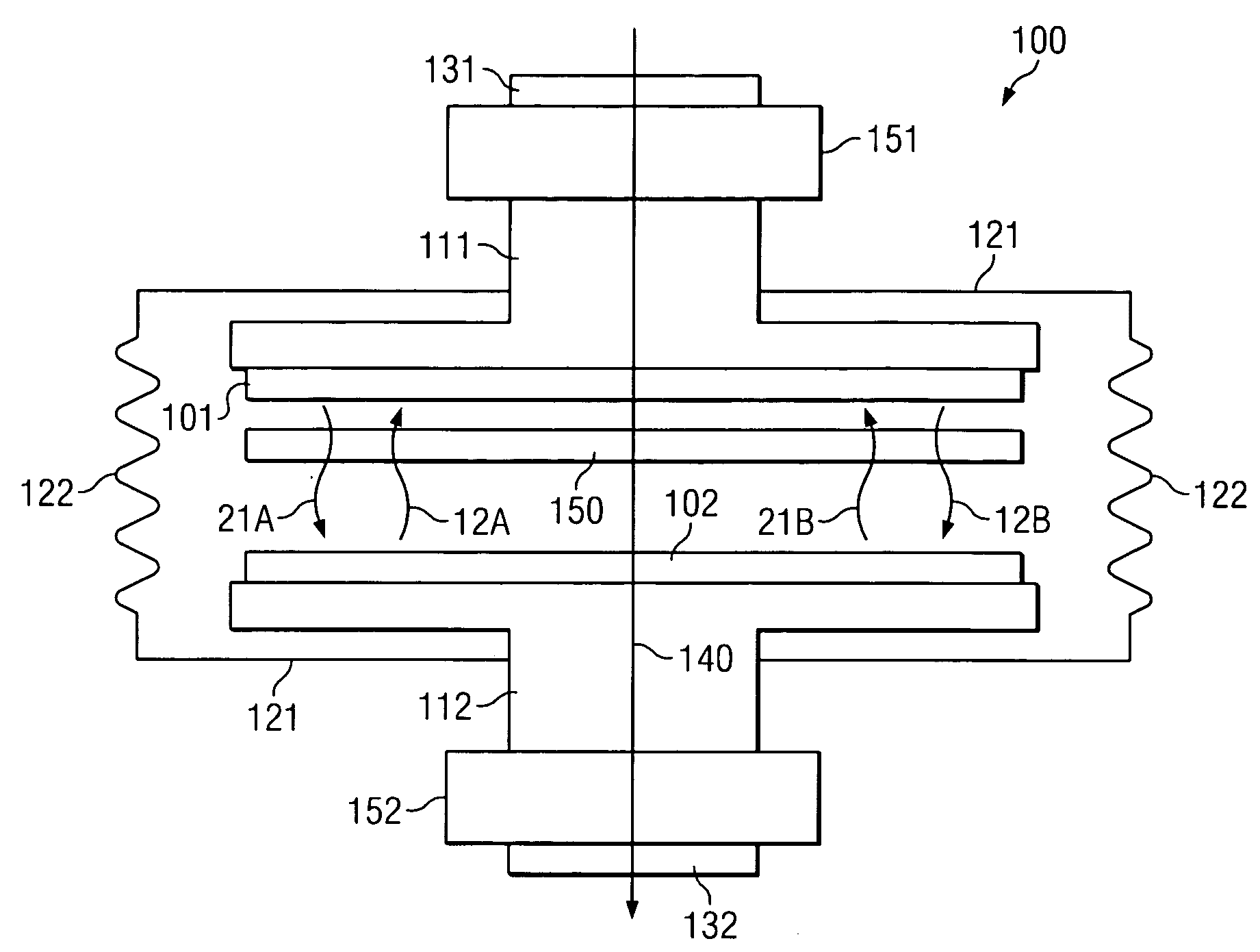
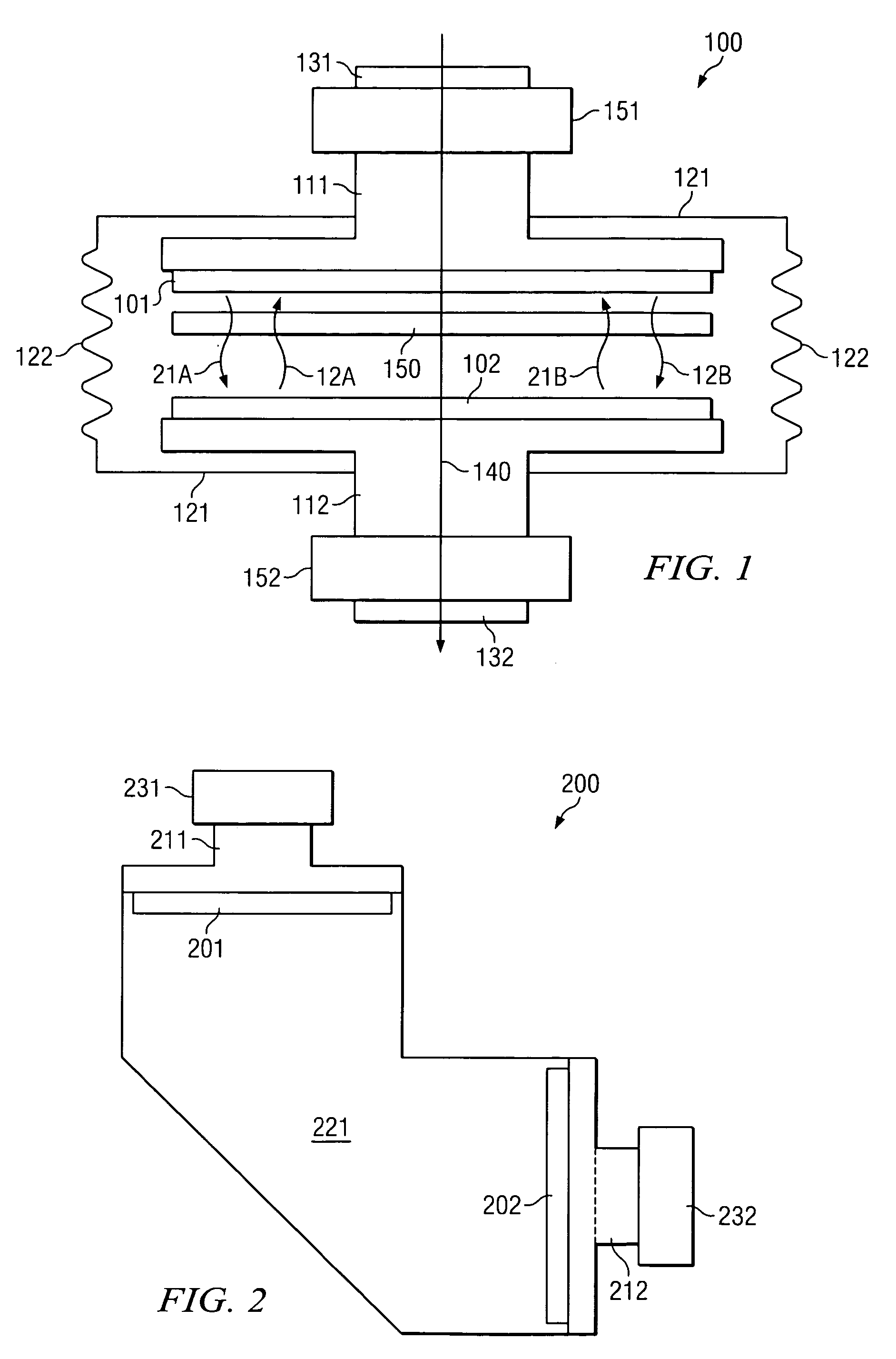
[0023] The present invention relates to a directional heat exchanger which may be used as a thermal energy diode, a temperature gain device, a constant heat flow rate regulator, a constant temperature regulator, and / or a heat pipe. The directional heat exchanger may simultaneously operate in more than one mode.

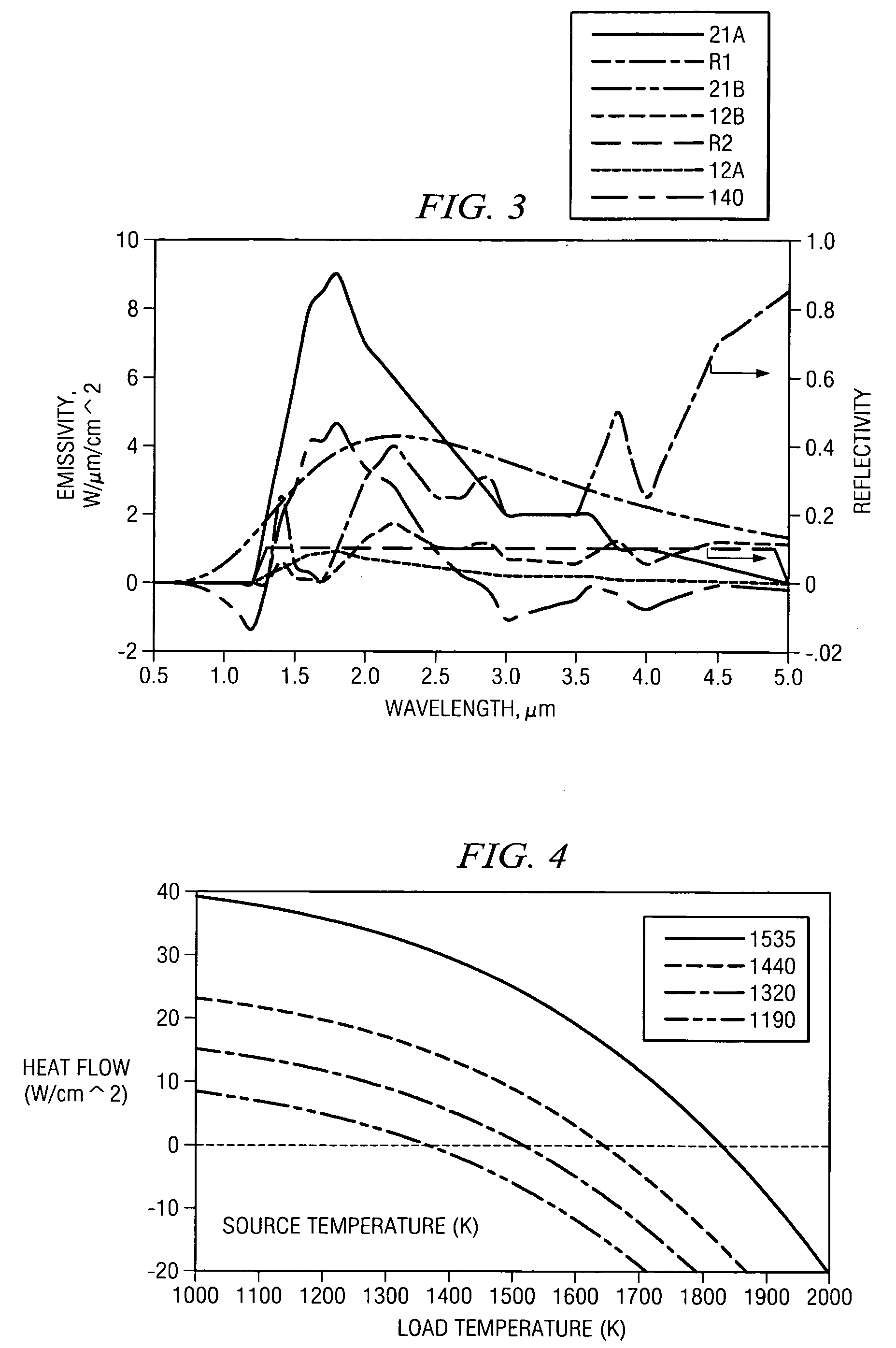
[0024] The directional heat exchanger consists of a thermally stimulated source optical emitter radiatively coupled to a load absorber. The source and load absorbers are selected such that radiated energy couples strongly from the source emitter to the load absorber, but couples weakly from the load absorber to the source emitter. There is net energy flow from the source emitter to the load absorber, with little energy flow in the opposite direction. For the two emitters to be in equilibrium, a temperature gain is observed, with the load absorber being at a higher temperature than the source emitter. Sufficient energy is coupled to remove useful thermal energy from the system...


PUM


Abstract

A directional heat exchanger system and method are provided. In one embodiment, the system includes a photonic band gap radiative emitter operable to be thermally coupled to a thermal energy source and accept thermal energy from the thermal energy source. The photonic band gap radiative emitter emits electromagnetic radiation which is incident on a surface of a load absorber.

Description

RELATED APPLICATIONS [0001] This application claims the priority benefit of U.S. Provisional Application Ser. No. 60 / 502,481, entitled “Directional Heat Flow Regulator,” filed Sep. 12, 2003.TECHNICAL FIELD OF THE INVENTION [0002] This invention relates generally to the field of thermal management and heat recovery and, more specifically to a directional heat exchanger. BACKGROUND OF THE INVENTION [0003] Many traditional heat transfer and temperature regulation devices are limited by the second law of thermodynamics. The second law of thermodynamics may be stated in numerous ways. Conceptually simplified, the second law of thermodynamics states that heat generally flows from relatively hotter objects to relatively colder objects. This is the case for thermal transfer in a closed system by conduction or convection. Radiative heat transfer between equal surface area black or gray bodies, without any conductive or convective heat transfer, will also result in a net heat flow from the re...

Claims


Application Information

Patent Timeline
Patent Type & Authority Applications(United States)
IPC IPC(8): G02B6/122
CPCG02B6/1225B82Y20/00
Inventor MARSHALL, ROBERT A.
Owner PRACTICAL TECH
Why Eureka
Try Eureka