Sensor component

a technology of sensor components and components, applied in the direction of measurement apparatus components, speed/acceleration/shock instrument details, measurement apparatus housings, etc., can solve the problems of difficult calibration, difficult access to sensors arranged in this manner, and difficult to calibrate, etc., to achieve high precision, rapid response characteristic, and sufficient stability

Active Publication Date: 2013-05-07
SCHOTT AG
View PDF15 Cites 5 Cited by
  • Summary
  • Abstract
  • Description
  • Claims
  • Application Information

AI Technical Summary

Benefits of technology

[0015]It is thus the object of the invention to provide a sensor component with which high precision and rapid response characteristic can be achieved in the measurements of physical properties of flowing media. Furthermore, the sensor component should have sufficient stability, especially in the region of the sensor section.
[0019]The integral arrangement can be produced especially simple and cost-effectively, e.g., by means of a punching process, in which the sensor section is punched out as a depression with lower wall thickness.

Problems solved by technology

Such an arrangement is especially problematic when the media concern aggressive media such as acids and / or high pressures prevail in the systems.
A further disadvantage of sensors arranged on the media side can be seen in such a way that that sensors arranged in this manner are not accessible or only with difficulty in the event of defects.
Calibration is also only possible with much effort.
The problem arises in an arrangement outside of the medium that there is imprecision in the measurements.
There is a further problem in that in the arrangement of a sensor on the outside wall of the conduit or the tank for example any changes in temperature can be detected only very imprecisely.

Method used


Image

  • Sensor component
  • Sensor component
  • Sensor component

Examples


Embodiment Construction

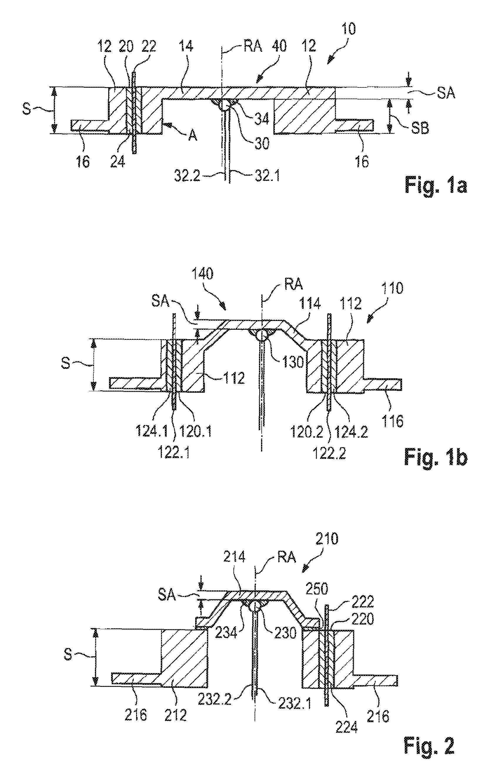
[0046]FIG. 1a shows a first embodiment of a sensor component 10 in accordance with the invention. The sensor component 10 is shown in a sectional view. The illustrated embodiment concerns a rotationally symmetrical component, with the section shown in FIG. 1a being rotated about the rotational axis RA, resulting in a three-dimensional rotationally symmetrical component in the form of a cylinder.

[0047]Other three-dimensional components in the form of a cuboid would be possible for example.

[0048]In the illustrated embodiment, sensor component 10 comprises a component section 12 and a sensor section 14. The component section 12 has a thickness or component section wall thickness S.

[0049]The sensor component shown in FIG. 1a can be further machined from a round blank by metal-cutting by turning or milling in such a way that an offset with a depth SB is milled by metal-cutting out of the blank. The component thickness S is thus reduced in the region of the sensor section 14 by the depth ...


PUM


Abstract

A leadthrough with a sensor section comprising a component section or tube section with a component wall thickness or tube wall thickness and least one sensor section for accommodating a sensor with a sensor wall thickness. The leadthrough with a sensor section is characterized in that the sensor wall thickness is smaller than half the component wall thickness or the tube wall thickness.

Description

CROSS-REFERENCE TO RELATED APPLICATIONS[0001]This application claims benefit of German application DE 10 2008 058 071.6 filed on Nov. 19, 2008 in the German Patent Office. The content of German application DE 10 2008 058 071.6 is hereby incorporated by reference in its entirety.STATEMENT REGARDING FEDERALLY-SPONSORED RESEARCH OR DEVELOPMENT[0002]Not ApplicableBACKGROUND OF THE INVENTION[0003]The invention relates to a sensor component, comprising a component section with a component wall and at least one sensor section for accommodating a sensor with a sensor wall, with the component wall having a component wall thickness and the sensor wall having a sensor wall thickness.[0004]Different types of sensors are used in the state of the art, e.g., temperature sensors, which detect the physical properties of a medium, e.g., a fluid or a gas. The medium whose physical properties such as the temperature are to be detected is guided in a conduit system for example or is stored in a containe...

Claims


Application Information

Patent Timeline
Patent Type & Authority Patents(United States)
IPC IPC(8): G01D11/24
CPCG01K1/143G01K13/02G01K1/18
Inventor FINK, THOMAS
Owner SCHOTT AG
Why Eureka
Try Eureka