Firestop drain assembly

a drain assembly and firestop technology, applied in water installations, sewer systems, construction, etc., can solve the problems of floor drains not meeting the f-rating and t-rating requirements of national building codes

Inactive Publication Date: 2013-05-14
CORNWALL KENNETH R
View PDF30 Cites 7 Cited by
  • Summary
  • Abstract
  • Description
  • Claims
  • Application Information

AI Technical Summary

Benefits of technology

[0008]The firestop drain assembly is mounted in a partition and prevents fire on one side of the partition from moving through the firestop drain assembly to the other side of the partition. The firestop drain assembly also prevents fire adjacent the second side of the partition from raising the temperature of the strainer of the drain above acceptable temperature levels. When heat from a fire adjacent the one side of the partition contacts the firestop extension and the drain pipe, the heat causes the firestop material to expand and fill the inner passageway of the housing of the firestop extension. The heat of the fire also softens or melts the drain pipe adjacent the fire including the portion of the drain pipe in the inner passageway of the housing of the firestop extension. The size and rate of expansion of the firestop material prevents the firestop material from contacting the drain pipe until the fire has sufficiently softened the drain pipe so that the expanding firestop material can crush the portion of the drain pipe located in the inner passageway of the housing of the firestop extension and completely close the inner passageway of the firestop drain assembly to prevent the fire from moving through the firestop drain assembly. The construction and size of the housing for the firestop extension, as well as the size and type of firestop material used, ensures that the drain pipe will soften before the firestop material contacts the drain pipe so that the firestop material can crush the drain pipe to completely block the firestop drain assembly. During a fire, the firestop drain assembly prevents the strainer of the drain from increasing in temperature more than approximately 325° F. (163° C.) above an ambient temperature of the strainer. When mounted in a concrete partition, the firestop drain assembly can achieve an F-rating and a T-rating of at least one (1) hour.

Problems solved by technology

In the past, floor drains were unable to achieve the F-rating and T-rating required by national building codes.

Method used


Image

  • Firestop drain assembly
  • Firestop drain assembly
  • Firestop drain assembly

Examples


first embodiment

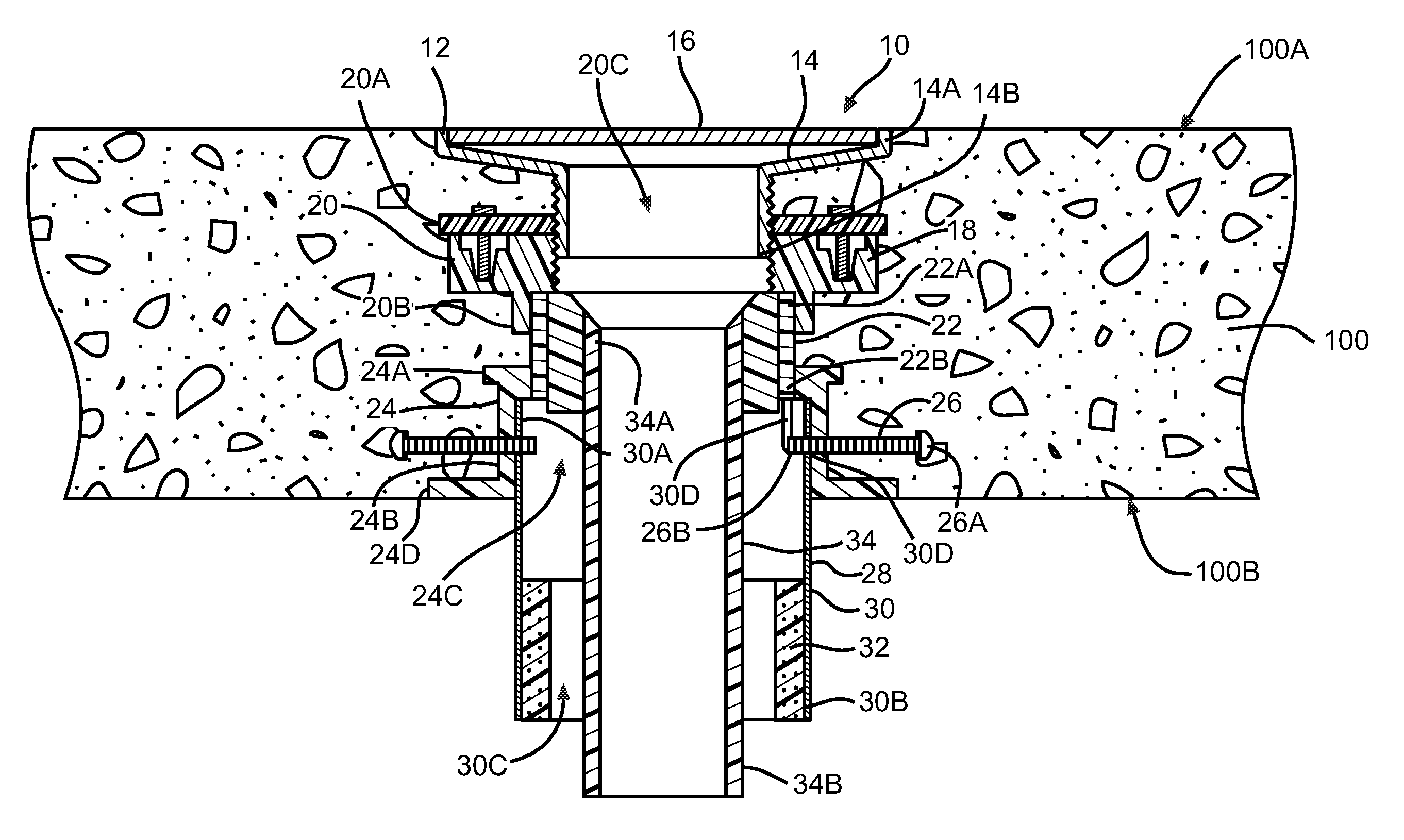
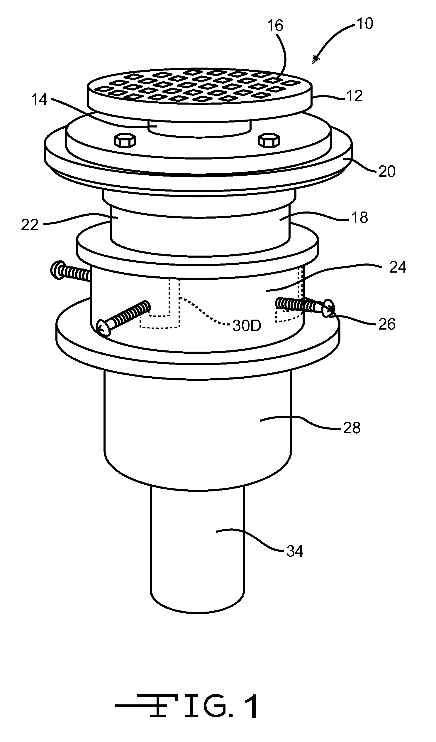
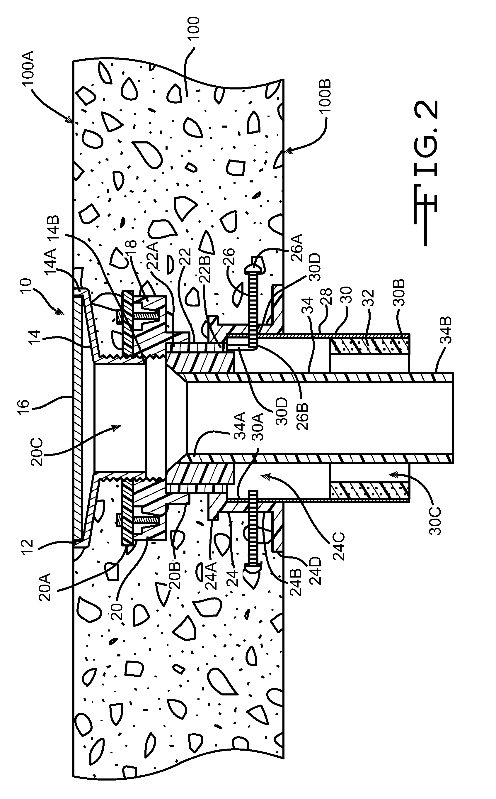
[0019]The configuration of the base 18, 218 and 318 of the firestop drain assembly 10, 210 and 310 depends on the type of partition in which the firestop drain assembly 10, 210 and 310 is to be used. In a first embodiment, the firestop drain assembly 10 is used in a wood form, concrete floor 100 (FIG. 2). In this embodiment, the base 18 includes a mounting flange 20, a coupling sleeve 22, and a coupling 24. The mounting flange 20 has opposed first and second ends 20A and 20B with an inner passageway 20C extending therebetween. The second end 14B of the drain housing 14 is mounted in the first end 20A of the mounting flange 20. In one (1) embodiment, the inner passageway 20C of the mounting flange 20 adjacent the second end 20B of the mount flange 20 is threaded. In this embodiment, the drain housing 14 has threads which engage the threads of the mounting flange 20. The threaded mating of the drain housing 14 and the mounting flange 20 allows for adjusting the height of the drain 12 ...

third embodiment

[0025]In the third embodiment, the first end 330A of the housing 330 of the firestop extension 328 is connected directly to the second end 320B of the mounting flange 320. The firestop extension 328 extends from the mounting flange 320 through the floor 300 and beyond the side 300B of the floor 300.

[0026]The drain pipe 34 has opposed first and second ends 34A and 34B with the first end 34A secured to the base 18, 218 or 318. The drain pipe 34 extends from the base 18, 218 or 318, through the inner passageway 30C, 230C and 330C of the housing 30, 230 and 330 of the firestop extension 28, 228 and 328 and beyond the second end 30B, 230B and 330B of the housing 30, 230 and 330 of the firestop extension 28, 228 and 328. The second end 34B of the drain pipe 34 is connected to the drain system (not shown). In one (1) embodiment, the drain pipe 34 has an essentially cylindrical shape. The drain pipe 34 is constructed of any well known material used in drainage systems. In one (1) embodiment...

second embodiment

[0032]In the second embodiment, for an approximately 2.5 inch (63.5 mm) concrete floor 200 on a fluted deck, the distance between the strainer 16 of the drain 12 and the top of the firestop material 232 is approximately 3.5 inches (89.9 mm). In this embodiment, the firestop drain assembly 210 has an F-rating and a T-rating of one (1) hour.

[0033]In the third embodiment, for an approximately 7.5 inch (190.5 mm) precast, hollow core concrete floor 300, the distance between the strainer 16 of the drain 12 and the top of the firestop material 332 is approximately 3.5 inches (89.9 mm). In this embodiment the firestop drain assembly 310 has a F-rating and a T-rating of two (2) hours.

[0034]The firestop drain assembly 10, 210 and 310 prevents fire from moving through a partition 100, 200 or 300 by way of the firestop drain assembly 10, 210 and 310. The firestop drain assembly 10, 210 and 310 prevents fire from moving from one side 100B, 200B and 300B of the partition to the other side 100A, ...


PUM


Abstract

A firestop drain assembly for mounting in a partition to prevent fire on one side of the partition from moving through the firestop drain assembly to the other side of the partition. The firestop drain assembly can achieve an F-rating and a T-rating of at least one (1) hour.

Description

CROSS REFERENCES TO RELATED APPLICATIONS[0001]This is a division of U.S. application Ser. No. 12 / 332,585 filed Dec. 11, 2008 which is a continuation-in-part of U.S. application Ser. No. 12 / 272,055 filed on Nov. 17, 2008 now abandoned which are hereby incorporated herein by reference in their entirety, except that the present application supersedes any portion of the above referenced applications which are inconsistent with the present application.STATEMENT REGARDING FEDERALLY SPONSORED RESEARCH OR DEVELOPMENT[0002]Not ApplicableBACKGROUND OF THE INVENTION[0003](1) Field of the Invention[0004]The present invention relates to a firestop drain assembly for use in a partition to prevent fire from moving through the partition. In particular, the present invention relates to a firestop drain assembly which prevents fire from moving through the partition before the temperature of the strainer increases above acceptable temperatures.[0005](2) Description of Related Art[0006]In the past, flo...

Claims


Application Information

Patent Timeline
Patent Type & Authority Patents(United States)
IPC IPC(8): E04B1/70
CPCE03F5/0407E03F5/041E03F2005/0413
Inventor CORNWALL, KENNETH R.
Owner CORNWALL KENNETH R
Why Eureka
Try Eureka