
Auto-phoropter interface and computer monitor filter

Inactive Publication Date: 2013-05-21
NORDSTROM STEVEN B
View PDF9 Cites 15 Cited by
  • Summary
  • Abstract
  • Description
  • Claims
  • Application Information

AI Technical Summary

Benefits of technology

The present invention is a vision testing system that can accept infrared signals from different manufacturers without needing pre-configuration. It also has the ability to adjust the light output through a filter with variable density.

Problems solved by technology

Chart projectors are limited in their use, however, as they have a finite number of tests available, require considerable maintenance and cannot present randomized eye charts.
Since the automated phoropters are new technology and relatively expensive, practitioners often objected to using older outdated chart projectors in combination with more sophisticated new technology.
With computerized vision testing, it is not possible to accurately produce these light levels in a consistent, repeatable manner using a standard CRT or LCD monitor.
One problem associated with the difficulty achieving correct light levels is the inability to produce the many shades of grey required for contrast testing if the light output of the monitor is reduced.
The brightness of the monitor may not be used to control the light level, because the quality of the image is reduced with reduced brightness and it is very tedious to restore the monitor to its original settings for subsequent tests.
The obvious solution of placing a filter over the monitor screen is inadequate because of the lack of accurate, stable filter densities and the difficulty of calibrating the monitor / filter combination to the correct light level.

Method used


Image

  • Auto-phoropter interface and computer monitor filter
  • Auto-phoropter interface and computer monitor filter
  • Auto-phoropter interface and computer monitor filter

Examples


first embodiment

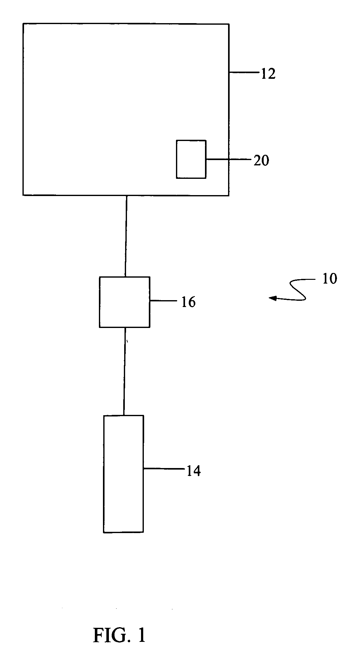
[0033]As depicted in FIG. 1, the invention 10 includes an auto-phoropter 12, a computer 14 with visual acuity testing software, and an interface 16. In this embodiment the auto-phoropter is an RT-5100.

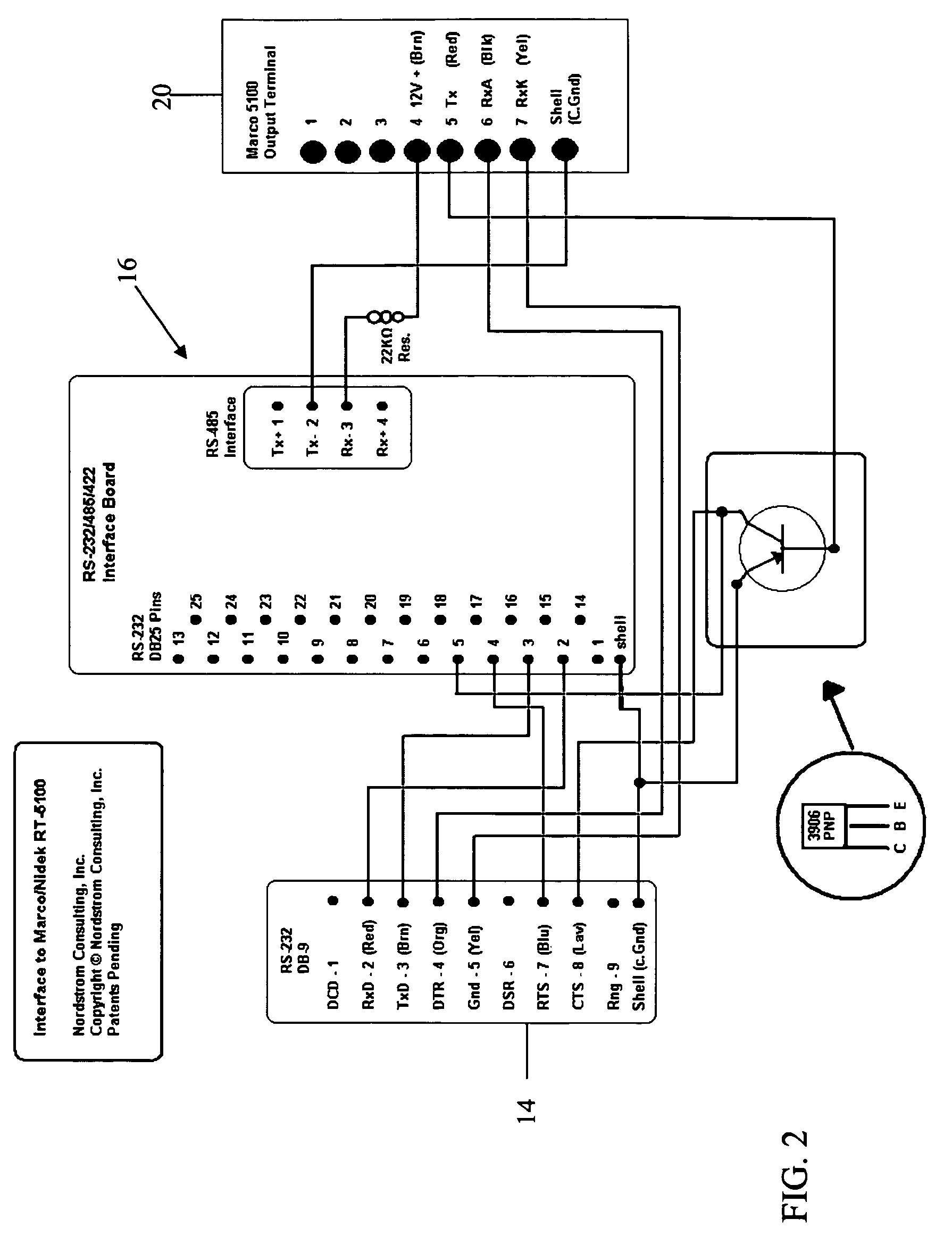
[0034]The auto-phoropter 12 includes a connection port 20. As shown in FIG. 2, connection port 20 has the following connections:

[0035]Pin 1—GND

[0036]Pin 2—IR_Rx (Infrared—not used in this embodiment)

[0037]Pin 3—IR_Tx (Infrared—not used in this embodiment)

[0038]Pin 4—+12 volts

[0039]Pin 5—W_Tx (wired)

[0040]Pin 6—W_RxA (wired)

[0041]Pin 7—W_RxK (wired)

[0042]Pin E—Frame Gnd

[0043]The interface 16 of this embodiment includes the following connections between connection port 20 of the auto-phoropter 12 and the computer 14, as shown in detail in FIG. 2.

[0044]The 12V line (pin 4) from the connection port 20, is connected to the Rx-terminal on an Aten IC-485SN RS485 to RS232 converter. This causes the RS-485 to RS-232 board to maintain a RS-232 pin 5 (25 pin configuration—CTS) at 5 volts which is...

second embodiment

[0053]Since the Aten IC-485SN RS-485 to RS-232 converter is used to provide a low voltage current loop from the 12v line of the connection port 20 to the W_Tx (wired transmit) line of the connection port 20, the RS-485 to RS-232 converter is not essential to this embodiment of the present invention and the wired interface used in the second embodiment may be freely substituted with no change in performance.

[0054]A second embodiment of the present invention 100 also includes an auto-phoropter 112, a computer 114 with visual acuity testing software, and an interface 116. In this embodiment the auto-phoropter is an RT-2100.

[0055]The auto-phoropter 112 includes a connection port 120. As shown in FIG. 4, connection port 120 has the following connections:

[0056]Pin 4—+12 volts

[0057]Pin 5—W_Tx (wired)

[0058]Pin 6—W_RxA (wired)

[0059]Pin 7—W_RxK (wired)

[0060]Pin E—Frame Gnd

[0061]The interface 116 of this embodiment includes the following connections between connection port 120 of the auto-phor...


PUM


Abstract

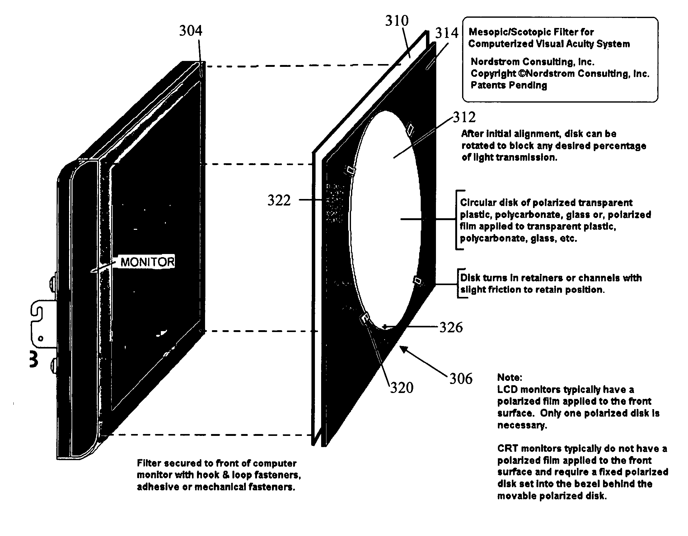
An interface for allowing communication between an auto-phoropter and a computer with visual acuity testing software. An adjustable filter for a computer monitor used with a computer with visual acuity testing software.

Description

RELATED APPLICATIONS[0001]This application claims the benefit of U.S. Provisional Application No. 60 / 940,810 filed May 30, 2007 and U.S. Provisional Application No. 60 / 965,010 filed Aug. 16, 2007 the entireties of which are incorporated herein.TECHNICAL FIELD[0002]The present invention relates, in general, to automated auto-phoropters and automated visual acuity testing systems and more particularly to an interface between an auto-phoropter and an automated visual acuity testing system. In addition, the present invention relates to a Mesoptic filter for a monitor for a computer with an automated visual acuity testing system.BACKGROUND[0003]Currently in the field of ophthalmology and optometry, automated systems are used to control auto-phoropters, chart projectors, and other equipment providing increased efficiency in the exam, including the capture and transfer of data to electronic medical records. Chart projectors are limited in their use, however, as they have a finite number of...

Claims


Application Information

Patent Timeline
IPC IPC(8): A61B3/02
CPCA61B3/0285
Inventor NORDSTROM, STEVEN B.
Owner NORDSTROM STEVEN B
Learn More