

Method and apparatus for applying multi-autofocusing (AF) using contrast AF
a multi-autofocus and contrast af technology, applied in the direction of instruments, printers, cameras, etc., can solve the problems of increasing the size and cost of the camera in order to achieve the external light af method, and the overall af speed is still low
- Summary
- Abstract
- Description
- Claims
- Application Information
AI Technical Summary
Benefits of technology
Problems solved by technology
Method used
Image

Examples
embodiment i
[0190]FIGS. 23 through 26 are flowcharts of an operation of the digital photographing apparatus 1 of FIG. 1.
[0191]FIG. 23 is a flowchart of a driving process (operation A1) of the digital photographing apparatus 1, according to an embodiment. In operation S2310, when the main switch SM of the digital photographing apparatus 1 is turned on, the mode of the digital photographing apparatus 1 is set by the manipulation unit 207 or the like. Then, lens information is required as an input to the lens 100 in order to operate the digital photographing apparatus 1 in operation S2320. The lens information corresponds to unique lens parameters stored in the lens memory 112 of FIG. 1, and is necessary for AF, AE, AWB, image quality control, etc.
[0192]In operation S2330, the imaging device 204 of FIG. 2 periodically starts photographing. Then, AE and AWB values are calculated in operation S2340, and a live view is displayed in operation S2350. Although the operations S2310 through S2350 are sequ...
embodiment 2
[0229]FIG. 10 is a schematic diagram of an interchangeable-lens digital photographing apparatus 1, according to another embodiment.
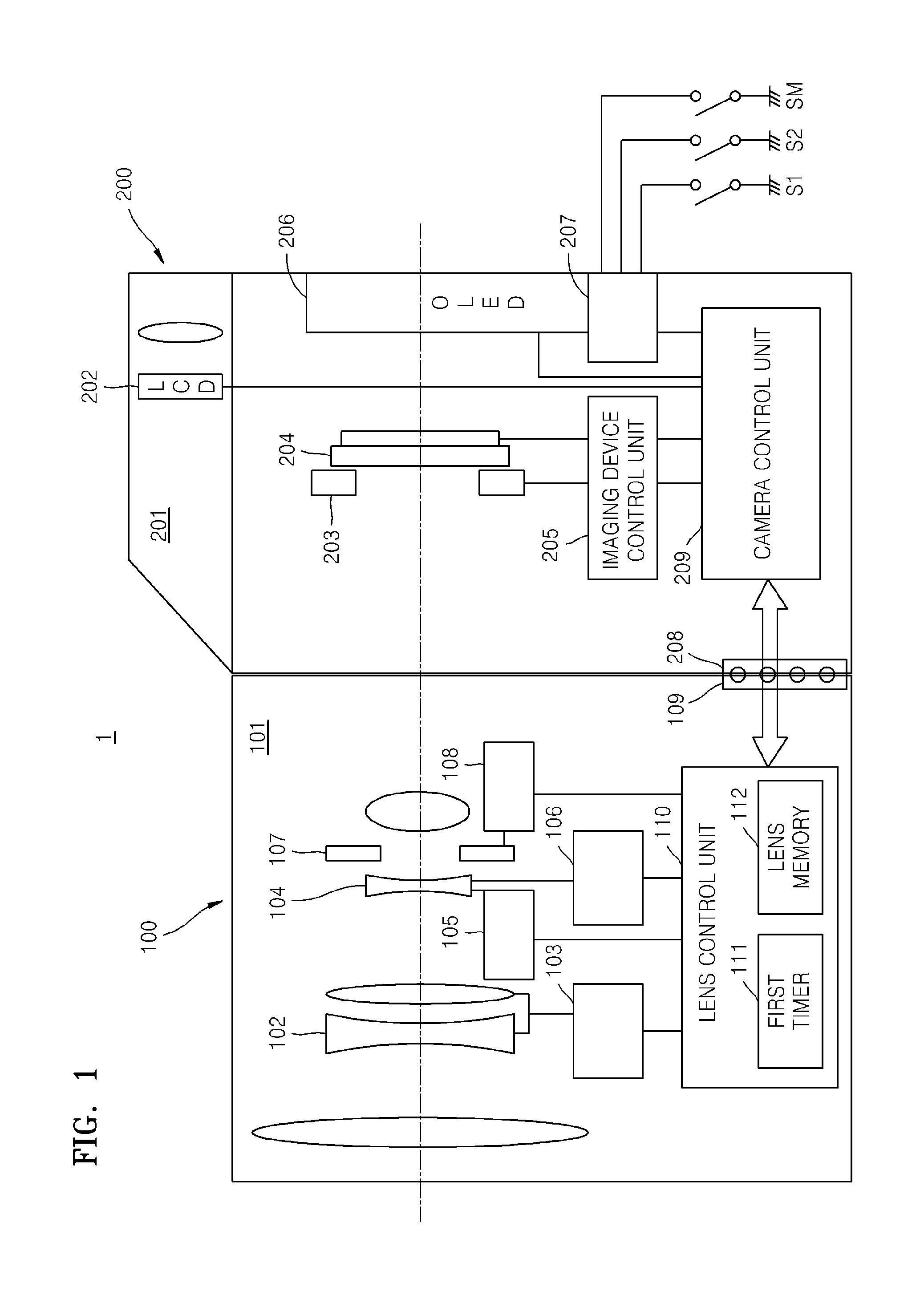
[0230]The lens driving actuator 105 and the focus lens position detecting sensor 106 are included in the image-forming optical system 101 in FIG. 1, whereas a camera which is an example of the digital photographing apparatus 1 of FIG. 10 includes an image-forming optical system 101 without a lens driving actuator and a focus lens position detecting sensor. Instead, a body unit 200 of the camera of FIG. 10 includes a lens driving actuator 230 for driving a focus lens group along an optical axis, and a position sensor 231 for sensing the position of the focus lens group, and a camera control unit 209 includes a camera memory 228.
[0231]The camera memory 228 stores an error value ΔIB due to unique information about a lens or a difference between the lens and the frequency of AF detection, and a correction value ΔIBoff that is changed according to a focus det...
embodiment 3
[0236]A digital photographing apparatus having a lens and a body unit integrally formed in one body will now be described by focusing on differences between the digital photographing apparatus having a lens and a body unit integrally formed in one body and the above-described digital photographing apparatuses 1.
[0237]FIG. 11 is a schematic diagram of a digital photographing apparatus 2 having a lens and a body unit integrally formed in one body, according to another embodiment.
[0238]The digital photographing apparatus 2 according to the present embodiment has a structure and a function similar to those of the digital photographing apparatus 1 of FIG. 1, so only differences therebetween will be described.
[0239]Since the digital photographing apparatus 2 according to the present embodiment includes a lens 100 and a body unit 200 integrally formed in one body, the lens 100 cannot be replaced. In addition, since the lens 100 and the body unit 200 are integrally formed in one body as des...
PUM
 Abstract
Description
Claims
Application Information