Lens holder driving device including fracture preventing member for suspension wires

a technology of driving device and lens holder, which is applied in the direction of printers, instruments, camera focusing arrangement, etc., can solve the problems of image quality degrading in compassion, ccd moving portion (a movable mechanism), and long taking time interval, so as to achieve the effect of increasing impact resistan

Active Publication Date: 2013-01-17
MITSUMI ELECTRIC CO LTD
View PDF6 Cites 98 Cited by
  • Summary
  • Abstract
  • Description
  • Claims
  • Application Information

AI Technical Summary

Benefits of technology

[0040]It is therefore an exemplary object of the present invention to provide a lens holder driving device which is capable of increasing impact resistance.

Problems solved by technology

However, the image stabilizing method of “the software stabilizing method” disclosed in the Patent Document 1 has a problem so that image quality degrades in compassion with the “optical method” which will later be described.
In addition, the image stabilizing method of the software stabilizing method has disadvantage so that a taking time interval becomes longer because processing of the software is included therein.
However, in “the sensor shift method” as disclosed in Patent Document 2, the CCD moving portion (a movable mechanism) becomes large.
It is therefore difficult in terms of size (outer dimensions, a height) to adopt the image stabilizer of the sensor shift method to a miniature camera for a mobile phone.
However, such image stabilizers (the image stabilizing devices) have problems in which structure is complicated and they are unsuited for miniaturization.
That is, like in the above-mentioned image stabilizer of the sensor shift method, it is difficult in terms of size (outer dimensions, a height) to adopt the image stabilizer of the lens shift method to the miniature camera for the mobile phone.
As a result, there is a problem in which the image stabilizer becomes large.
As a result, the image stabilizer becomes large.
Furthermore, inasmuch as there are the rotary axes in “the optical unit tilting method”, there is a problem in which friction is produced between a hole and an axis and it results in exhibiting hysteresis.
As a result, there is a problem in which the optical photography device becomes large.
Therefore, there is a problem in which the number of parts is increased.
In also the lens driving device disclosed in Patent Document 15, in the manner similar to the lens driving device disclosed in Patent Document 14, there is a problem in which the number of parts is increased.
It is therefore feared that the plurality of suspension wires may fracture in a case where the plurality of suspension wires are subjected to force in a direction to extend due to drop impact of the image stabilizer or the like.
As a result, in the manner similar to the image stabilizer disclosed in Patent Document 16, it is feared that the four suspension wires may fracture in a case where the four suspension wires are subjected to force in a direction to extend due to drop impact of the lens driving device or the like.
However, the lens driving device disclosed in Patent Document 15 does not take into account the fear of fracture of the wires in a case where force applies to the wire in a direction to extend due to drop impact or the like.

Method used


Image

  • Lens holder driving device including fracture preventing member for suspension wires
  • Lens holder driving device including fracture preventing member for suspension wires
  • Lens holder driving device including fracture preventing member for suspension wires

Examples


Embodiment Construction

[0069]Referring now to Figures, the description will proceed to exemplary embodiments of the present invention.

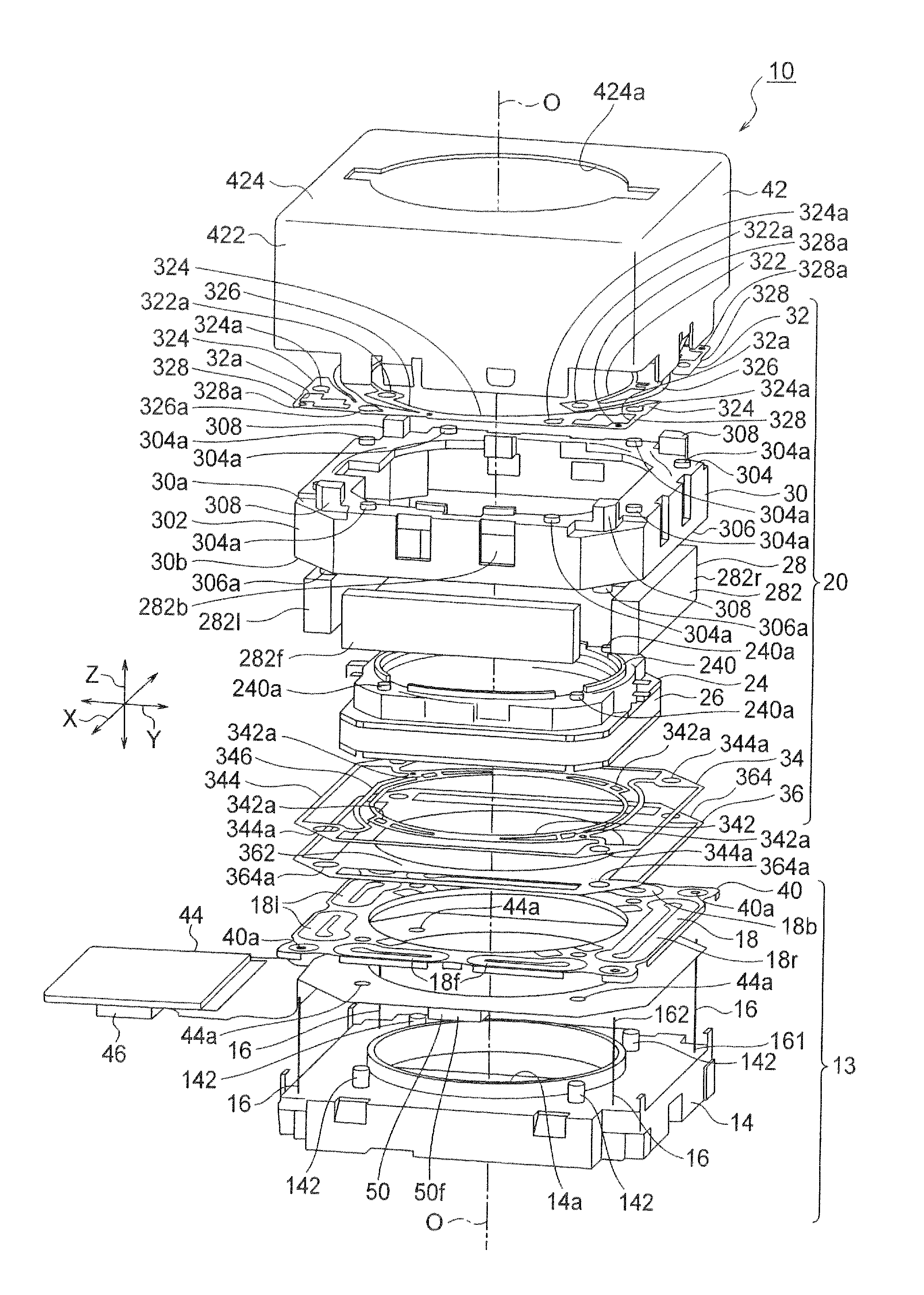
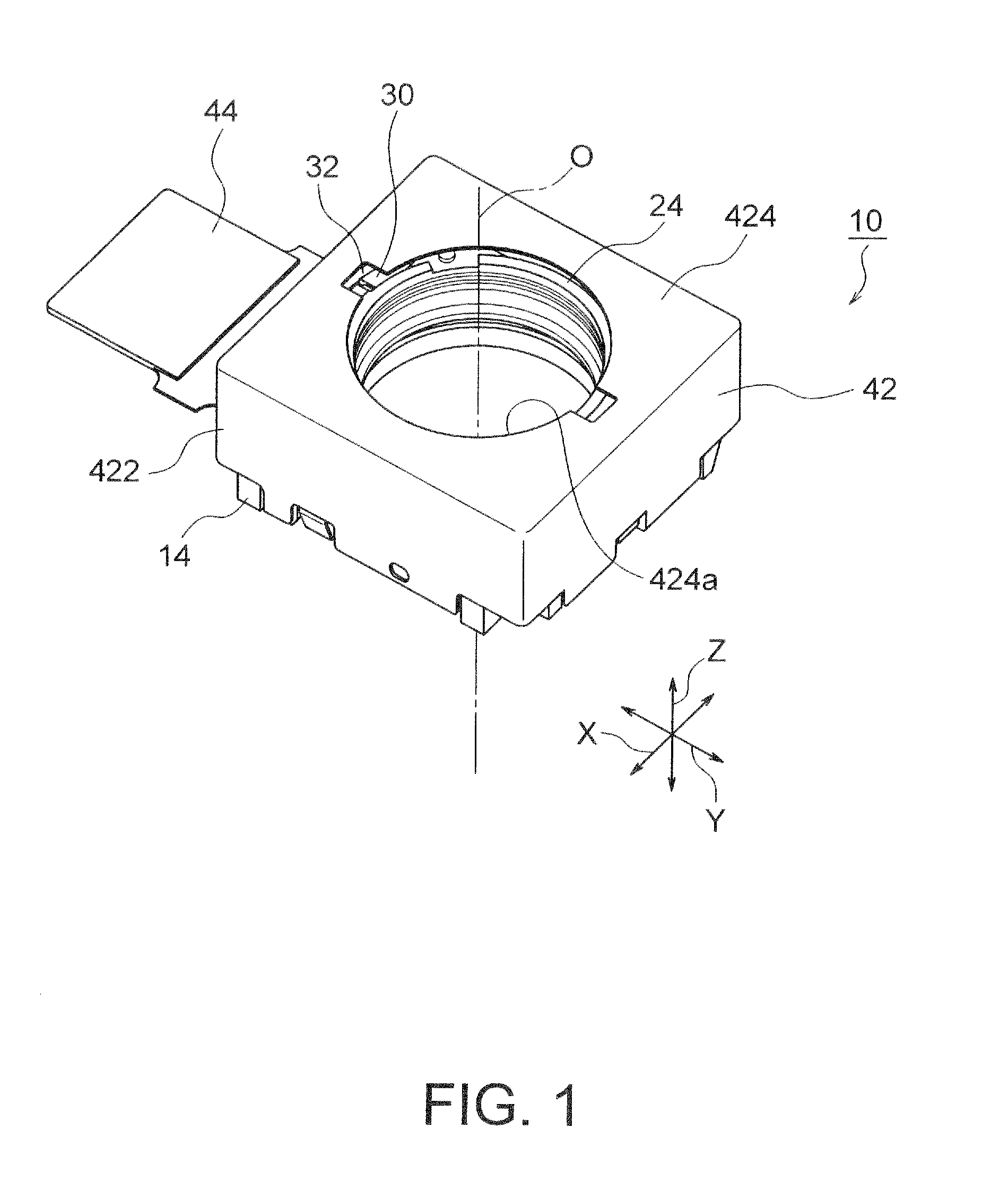
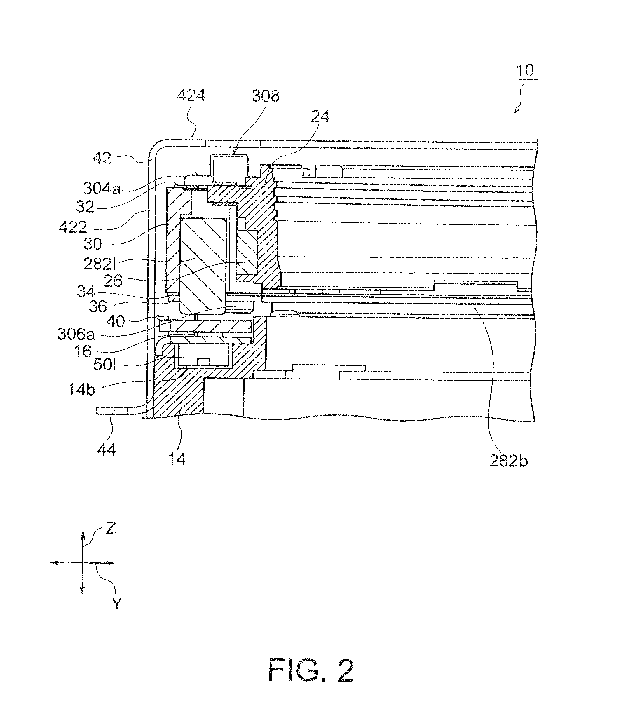
[0070]Referring to FIGS. 1 through 3, the description will proceed to a lens holder driving device 10 according to a first exemplary embodiment of this invention. FIG. 1 is an external perspective view of the lens holder driving device 10. FIG. 2 is a partial vertical cross sectional view of the lens holder driving device 10. FIG. 3 is an exploded perspective view of the lens holder driving device 10.

[0071]Herein, in the manner shown in FIGS. 1 through 3, an orthogonal coordinate system (X, Y, Z) is used. In a state illustrated in FIGS. 1 through 3, in the orthogonal coordinate system (X, Y, X), an X-axis direction is a fore-and-aft direction (a depth direction), a Y-axis direction is a left-and-right direction (a width direction), and a Z-axis direction is an up-and-down direction (a height direction). In addition, in the example being illustrated in FIGS. 1 through 3, the...


PUM


Abstract

A lens holder driving device includes an auto-focusing lens holder driving portion moving a lens holder holding a lens barrel along an optical axis, and an image stabilizer portion stabilizing image blurred by moving the auto-focusing lens holder driving portion in first and second directions which are orthogonal to the optical axis and which are perpendicular to each other. The image stabilizer portion includes: a fixed portion disposed apart from the auto-focusing lens holder driving portion in the direction of the optical axis; a plurality of suspension wires having first end portions fixed to the fixed portion at outer regions thereof, extending along the optical axis, having second end portions fixed to the auto-focusing lens holder driving portion, and swingably supporting the auto-focusing lens holder driving portion in the first direction and the second direction; and a fracture preventing member preventing the suspension wires from fracturing.

Description

[0001]This application is based upon and claims the benefit of priority from Japanese Patent Application No. 2011-157082, filed on Jul. 15, 2011, the disclosure of which is incorporated herein in its entirety by reference.BACKGROUND OF THE INVENTION[0002]This invention relates to a lens holder driving device and, in particular, to a lens holder driving device capable of picking up a static image without blurry images by stabilizing the blurry images (movement) occurring upon shooting the static image using a miniature camera for a mobile terminal.[0003]Hitherto, various lens holder driving devices has been proposed which are capable of taking photographs with a high degree by stabilizing blurry images on an image-forming surface although there are blurry images (movement) upon shooting the static image.[0004]As image stabilizing methods, “optical methods” such as a sensor shift method or a lens shift method and “a software stabilizing method” for stabilizing the blurry images using ...

Claims


Application Information

Patent Timeline
Patent Type & Authority Applications(United States)
IPC IPC(8): G02B27/64G02B7/09
CPCG03B3/10G02B27/646G03B2205/0015H04N5/2328H04N5/2257G03B2205/0069G02B7/08H04N23/57H04N23/685G02B7/09
Inventor SUGAWARA, MASAYOSHIMORIYA, AKIHIROSATO, KEIICHIARIJI, MAKOTOAJIKI, SATOSHI
Owner MITSUMI ELECTRIC CO LTD
Why Eureka
Try Eureka