Image photographing apparatus
- Summary
- Abstract
- Description
- Claims
- Application Information
AI Technical Summary
Benefits of technology
Problems solved by technology
Method used
Image
Examples
first embodiment
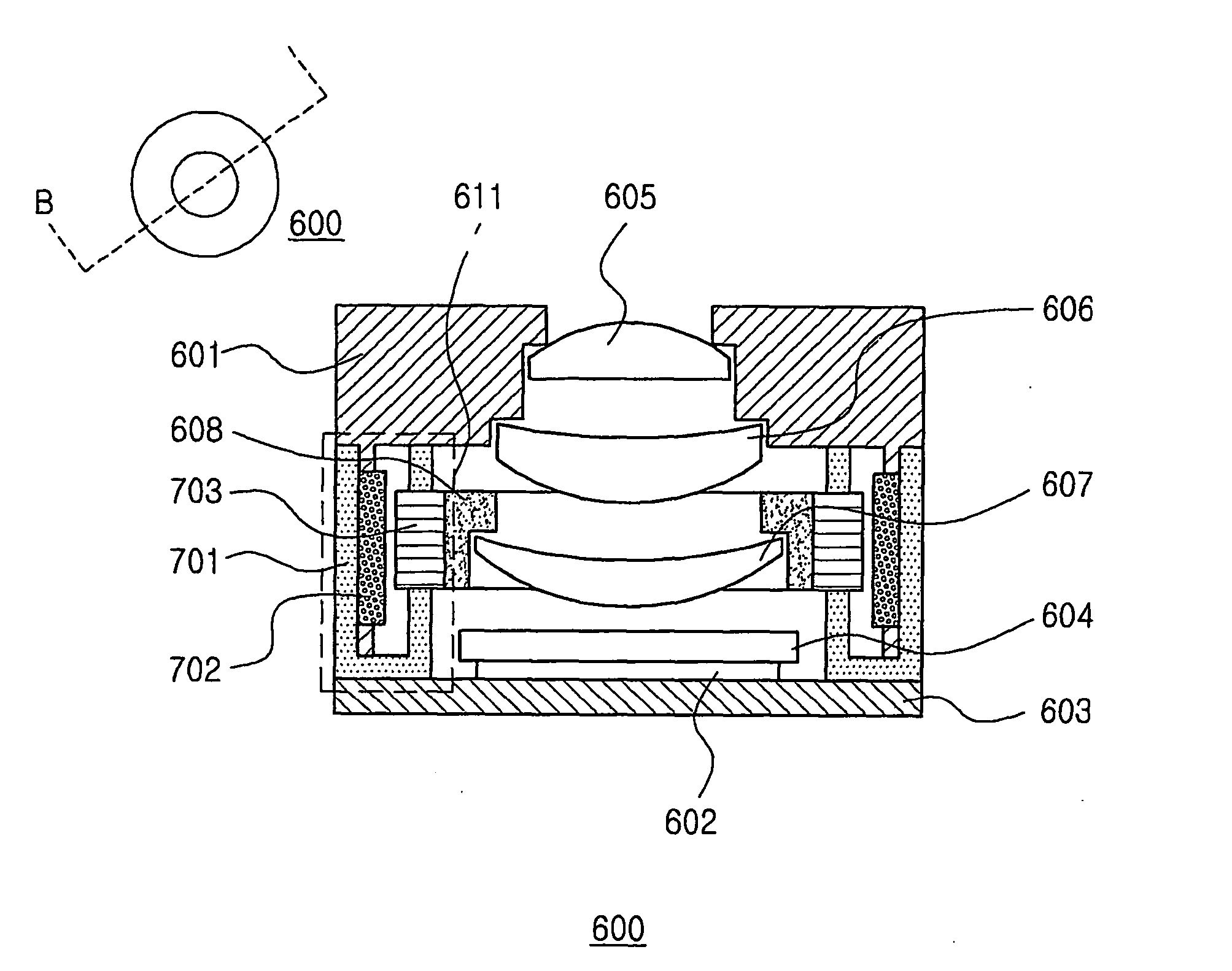
[0135]FIGS. 6-9 are views showing the constitution of an image photographing apparatus according to the first embodiment of the present invention. Herein, the image photographing apparatus 600 according to the first embodiment of the present invention comprises:
[0136] a fixing lens group 605, 606 having an external lens barrel 601, a photographing element 602, a photographing element base 603, an ultraviolet protection filter 604 and a lens;
[0137] a compensation lens group 607 having one or more lenses;
[0138] a focus driving part 608 mounting the compensation lens group 607; and
[0139] a guide shaft 609 guiding the transfer of the focus driving part 608.
[0140] In addition, a focus actuator 611 for moving the focus driving part 608 in the direction of an optical axis is installed between the focus driving part 608 and the external lens barrel 601. The focus actuator 611 further comprises a driving coil 703 for generating a driving force by flowing current installed outside of the...
second embodiment
[0211]FIGS. 31 and 32 are views showing the constitution of an image photographing apparatus according to the second embodiment of the present invention. That is, FIGS. 31 and 32 are views showing the mounting state of a zoom lens group 651 varying a magnification, a zoom driving part 653 and a zoom actuator. By referring to FIG. 31, in a predetermined cross-sectional view of the image photographing apparatus taken along the line A-A, the image photographing apparatus 600 comprises a zoom driving part 653 having an external lens barrel 601, a photographing lement 602, a photographing element base 603, an untraviolet protection filter 604, a fixing lens group 605, a zoom lens group 651, a compensation lens group 607, and the zoom lens group 651; a focus driving part 608 mounting the compensation lens group 607; and a guide shaft 609 guiding the transfer of the two driving parts.
[0212] The image photographing apparatus 600 in a predetermined cross-sectional view taken along the other...
third embodiment
[0224]FIG. 40 is a view showing the constitution of an image photographing apparatus according to the third embodiment. The image photographing apparatus according to the present invention by referring to FIG. 40 comprises a compensation lens group 4200; a focus actuator 4300 for adjusting the focus of the compensation lens group 4200; a focus driving part 4250 installed between the compensation lens group and the focus actuator 4300 for setting the initial position of the compensation lens group 4200; a compensation driving part 4400 for supporting the focus actuator 4300; a zoom driving part 4700 for supporting the zoom lens group 4600 and the displacement lens group 4600; a zoom actuator 4500 for driving the compensation driving part 4400 to move the compensation lens group 4200 along a first moving trajectory, and driving the zoom driving part 4700 to move the displacement lens group 4600 along a second lens group 4200; a photographing element 4800 for photographing an image of ...
PUM
 Abstract
Description
Claims
Application Information
 - R&D
- Intellectual Property
- Life Sciences
- Materials
- Tech Scout
- Unparalleled Data Quality
- Higher Quality Content
- 60% Fewer Hallucinations
Browse by: Latest US Patents, China's latest patents, Technical Efficacy Thesaurus, Application Domain, Technology Topic, Popular Technical Reports.
© 2025 PatSnap. All rights reserved.Legal|Privacy policy|Modern Slavery Act Transparency Statement|Sitemap|About US| Contact US: help@patsnap.com


