Sheet conveying apparatus with inclined surface against which the sheet abuts and image forming apparatus having same

a conveying apparatus and a technology of abutting a surface, which are applied in the direction of electrographic process apparatus, thin material handling, instruments, etc., can solve the problems of paper jams, paper jams, and easy jamming of paper, and achieve the effect of reducing paper jams

Active Publication Date: 2013-05-21
CANON KK
View PDF17 Cites 12 Cited by
  • Summary
  • Abstract
  • Description
  • Claims
  • Application Information

AI Technical Summary

Benefits of technology

[0036]The present invention has been achieved in view of the above circumstances and provides a sheet conveying apparatus and an image forming apparatus in which paper jams can be reduced and shifting in a horizontal direction of the sheet can be corrected.
[0038]According to the present invention, shifting in the width direction of the sheet can be corrected without causing paper jams.

Problems solved by technology

However, in such conventional sheet conveying apparatuses, shifting of the sheet may occur in the width direction (thrust direction) during conveyance of the sheet.
Further, the wearing leads to sliding resistance between the sheet side edge and the reference guide 24, thereby causing paper jams easily.
In this case, unless the reference guide side of the sheet S is not deflected as shown in FIG. 17(b), the sheet S cannot be guided, resulting in paper jams.
Even if the edge of the sheet can be guided while the sheet S is deflected, when the path interval PT4 is narrow, it is difficult to deflect the sheet S.
Then, the resistance becomes conveying resistance, thereby causing paper jams.
This causes rubbing and wearing.
Then, paper jams are caused by the conveying resistance of the sheet S.
However, as the duration of use becomes longer, each corner portion of the metallic member 170 is significantly scratched and worn by the sheet side edge to be guided.
As a result, paper jams are caused by sliding resistance.
As a result, the accuracy of the sheet position is reduced.

Method used


Image

  • Sheet conveying apparatus with inclined surface against which the sheet abuts and image forming apparatus having same
  • Sheet conveying apparatus with inclined surface against which the sheet abuts and image forming apparatus having same
  • Sheet conveying apparatus with inclined surface against which the sheet abuts and image forming apparatus having same

Examples


Embodiment Construction

[0059]Herein after, an exemplary embodiment of the present invention will be specifically described with reference to the drawings.

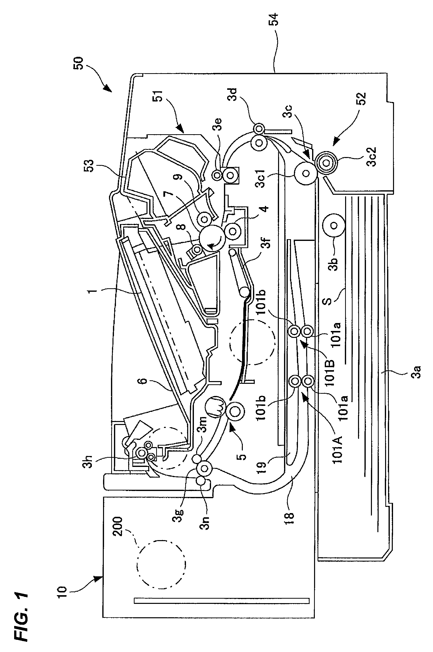
[0060]FIG. 1 is a diagram illustrating the schematic structure of a laser beam printer that is one example of an image forming apparatus having a sheet conveying apparatus according to the embodiment of the present invention.

[0061]In FIG. 1, the laser beam printer 50 forms an image by an electrophotographic system. The laser beam printer 50 has an image forming portion 51 that performs image formation and a feeding portion 52 that feeds a sheet S to the image forming portion 51 one by one. Further, the laser beam printer 50 is optionally equipped with a duplex unit 10 that is a sheet conveying apparatus for feeding the sheet S to the image forming portion 51 again so that an image is formed on back side after image formation on one side in order to form images on the duplex side of the sheet S.

[0062]Here, the image forming portion 51 has a process cartri...


PUM


Abstract

A sheet conveying apparatus has a reference guide in which a reference surface that is elongated in a sheet conveying direction and abuts against an end portion of a sheet, an inclined surface which is provided upstream of the reference guide and which is inclined in a width direction intersecting with the sheet conveying direction so that an edge of the sheet is guided, the inclined surface intersecting the reference guide at an intersection, a sheet guide portion, a passage portion having an upstream area which is wider than the sheet guide portion in a vertical direction, a downstream area which is narrower than the upstream area in a vertical direction, and an inclined guide which is provided between the inclined surface and the reference surface, wherein a position of an upstream edge of the downstream area is provided between the intersection and the oblique conveying unit.

Description

BACKGROUND OF THE INVENTION[0001]1. Field of the Invention[0002]The present invention relates to a sheet conveying apparatus and an image forming apparatus.[0003]2. Description of Related Art[0004]A conventional example of an image forming apparatus such as an electro-photographic printer includes an image forming apparatus in which a sheet in which an image is formed on one surface is reversed and conveyed to an image forming portion again, thereby forming the image on back side of the sheet. Such an image forming apparatus has a sheet conveying apparatus which reverses the sheet in which the image is formed on one surface and conveys it to the image forming portion again.[0005]In such a conventional sheet conveying apparatus, when the sheet is conveyed to the image forming portion again, the sheet may be skew-fed during conveyance. When the image is formed on back side, the sheet and the image may be shifted. This is because when the image is formed on a second surface (back side)...

Claims


Application Information

Patent Timeline
Patent Type & Authority Patents(United States)
IPC IPC(8): B65H9/16B65H85/00B65H9/00
CPCG03G15/232G03G15/6579G03G15/6567G03G15/6564G03G2215/00565G03G15/235G03G15/1665
Inventor INUI, FUMIKI
Owner CANON KK
Why Eureka
Try Eureka