Card edge connector

a card edge and connector technology, applied in the direction of coupling device connection, two-part coupling device, electrical apparatus, etc., can solve the problem of unaddressed need in the ar

Active Publication Date: 2013-05-28
LOTES
View PDF8 Cites 9 Cited by
  • Summary
  • Abstract
  • Description
  • Claims
  • Application Information

AI Technical Summary

Benefits of technology

[0007]In one aspect, the present invention is directed to a card edge connector, in which a first contact arm has a long elastic arm, thereby achieving excellent elasticity to avoid getting fatigued easily.
[0010]In the embodiments of the present invention, the first elastic section extends backwards from the first connecting portion, the first contact arm extends forwards from the rear end of the first elastic section, that is, the first contact arm is formed by bending and extending the first connecting portion backwards and then forwards, totally twice, so that the length of the elastic arm of the first contact arm is the sum of the length of the first contact arm and the length of the first elastic section, which is equivalent to that the length of the elastic arm of the first contact arm is increased by the length of the first elastic section. Therefore, the elastic arm of the first contact arm is long and elastic, thereby preventing the first contact arm from getting fatigued easily after being pressed long by an electronic card.

Problems solved by technology

Therefore, a heretofore unaddressed need exists in the art to address the aforementioned deficiencies and inadequacies.

Method used


Image

  • Card edge connector
  • Card edge connector
  • Card edge connector

Examples


first embodiment

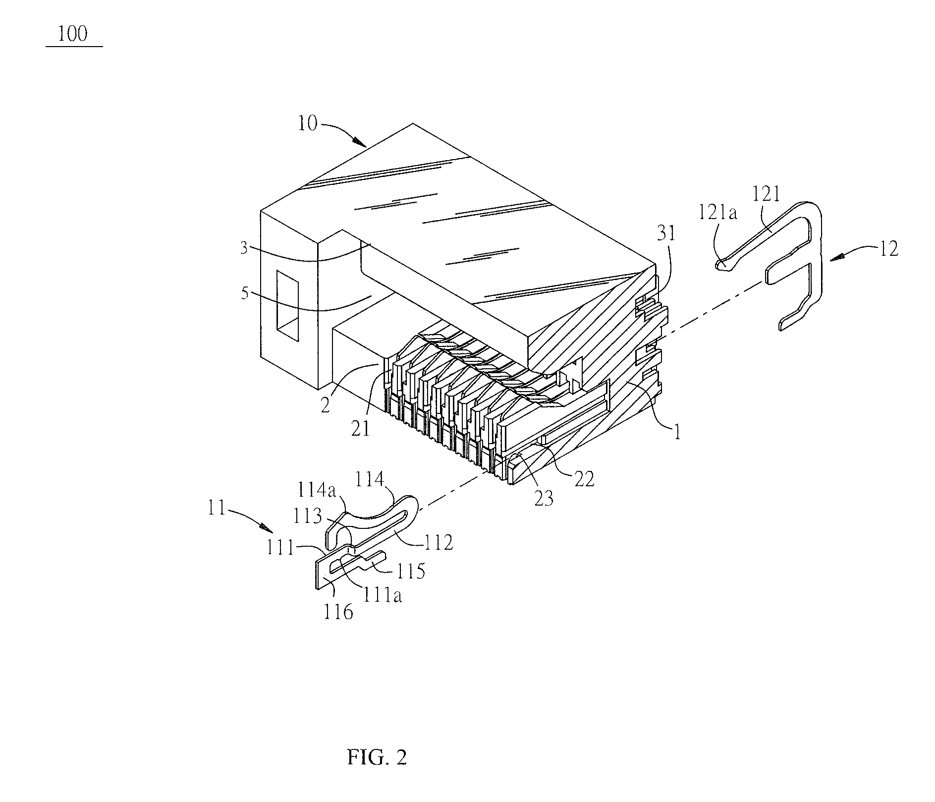
[0024]Referring to FIG. 2 and FIG. 3, the present invention is described briefly below. A card edge connector 100 is a single layer card edge connecter, and includes an insulating body 10 having a base body 1 disposed lengthwise. A first body 2 and a second body 3 extend forwards from the base body 1. The second body 3 is above the first body 2. The first body 2, the second body 3, and the base body 1 collectively enclose a first insertion space 5. The first body 2 is disposed with multiple recessed first receiving slots 21, and the second body 3 is disposed with multiple recessed second receiving slots 31. The first receiving slots 21 and the second receiving slots 31 are all in communication with the first insertion space 5. A recessed first retaining slot 22 is disposed at the first body 2 and a side wall of each of the first receiving slots 21.

[0025]Multiple first terminals 11 are secured in the first receiving slots 21. Each of the first terminals 11 has a first retaining porti...

second embodiment

[0026]FIGS. 4-10 are the card edge connector 100 according to the present invention, and the embodiment is a common embodiment in actual applications. The card edge connector 100 of the present invention is further described below with reference to FIGS. 4-10 and the specific embodiment.

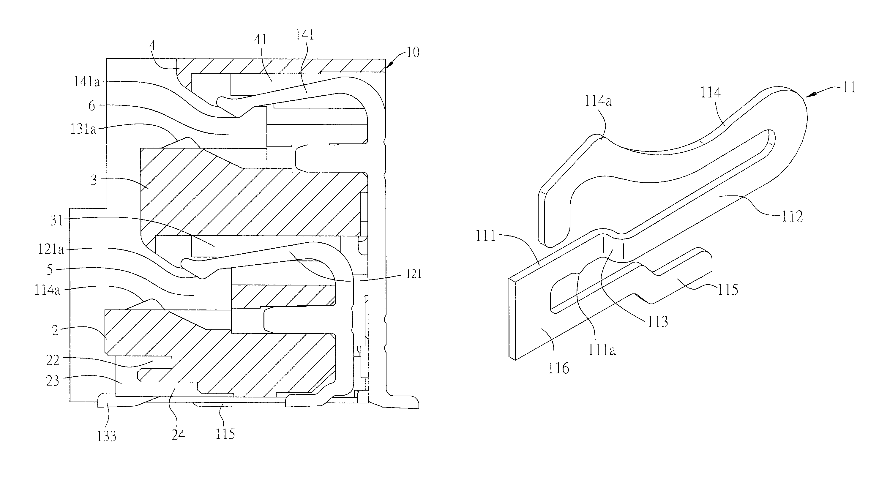
[0027]Referring to FIG. 4, the embodiment of the card edge connector 100 according to the present invention is a dual-layer card edge connector, and includes an insulating body 10, and multiple first terminals 11, multiple second terminals 12, multiple third terminals 13, and multiple fourth terminals 14 received in the insulating body 10.

[0028]Referring to FIG. 4, the insulating body 10 includes a base body 1 disposed lengthwise. A first body 2, a second body 3, and a third body 4 extend forwards from the base body 1, and are disposed sequentially from bottom to top. That is to say, the second body 3 is above the first body 2, and the third body 4 is above the second body 3. The first body 2, the se...


PUM


Abstract

A card edge connector includes an insulating body having a base body, multiple first terminals, and multiple second terminals. A first body and a second body extend from a front end of the base body sequentially from bottom to top. Multiple recessed first receiving slots are disposed at the first body. A recessed first retaining slot is disposed at the first body and a side wall of each of the first receiving slots. Each of the first terminals has a first retaining portion retained in the first retaining slot with a first connecting portion bent and extends laterally thereof. A first elastic section extends forwards from the first connecting portion and located in the first receiving slot. A first contact arm extends forwards from the rear end of the first elastic section and has a first contact portion which enters the first insertion space.

Description

CROSS-REFERENCE TO RELATED APPLICATIONS[0001]This non-provisional application claims priority under 35 U.S.C. §119(a) on Patent Application No. 201120369322.5 filed in P.R. China on Oct. 7, 2011, the entire contents of which are hereby incorporated by reference.[0002]Some references, if any, which may include patents, patent applications and various publications, may be cited and discussed in the description of this invention. The citation and / or discussion of such references, if any, is provided merely to clarify the description of the present invention and is not an admission that any such reference is “prior art” to the invention described herein. All references listed, cited and / or discussed in this specification are incorporated herein by reference in their entireties and to the same extent as if each reference was individually incorporated by reference.FIELD OF THE INVENTION[0003]The present invention generally relates to a card edge connector, and more particularly to a card ...

Claims


Application Information

Patent Timeline
Patent Type & Authority Patents(United States)
IPC IPC(8): H01R24/00
CPCH01R12/73H01R12/721H01R12/57
Inventor WANG, YONG FU
Owner LOTES
Why Eureka
Try Eureka