Reconfigurable beam-forming-network architecture

a beam-forming network and reconfigurable technology, applied in the direction of antennas, electrical equipment, radio transmission, etc., can solve the problems of bfn lack of reconfigurability, business conditions subject to unpredictable changes, telecommunication satellites have an ever-increasing operational lifespan, etc., and achieve modular and scalable design.

Active Publication Date: 2013-05-28
EUROPEAN SPACE AGENCY
View PDF9 Cites 8 Cited by
  • Summary
  • Abstract
  • Description
  • Claims
  • Application Information

AI Technical Summary

Benefits of technology

[0024]An aim of the invention is to provide an efficient, modular and scalable design solution for reconfigurable BFNs capable of supporting various multi-beam configurations.
[0025]Another aim of the invention is to provide a reconfigurable BFN architecture which can be easily adapted to several possible antenna architectures.
[0026]Still another aim of the invention is to provide a reconfigurable BFN architecture which can be used both in transmission and in reception, even in the case of digital implementation.

Problems solved by technology

Telecommunication satellites have an ever-increasing operational lifespan, and business conditions are subject to unpredictable changes.
The main limitation of this BFN is its lack of reconfigurability.
The complexity of such a network would make it impractical for many applications: simpler solutions retaining sufficient (although not complete) flexibility are therefore necessary.
The complexity saving provided by these solutions is, however, insufficient for many applications, particularly in the field of telecommunications.
An additional drawback of the prior art architectures is that the digital implementations of transmit and receive BFN may be drastically different from each other: this is due to the fact that digital signal dividers and combiners, unlike their analog counterparts, are intrinsically non-reciprocal devices and have completely different structures and implementations.

Method used


Image

  • Reconfigurable beam-forming-network architecture
  • Reconfigurable beam-forming-network architecture
  • Reconfigurable beam-forming-network architecture

Examples


Embodiment Construction

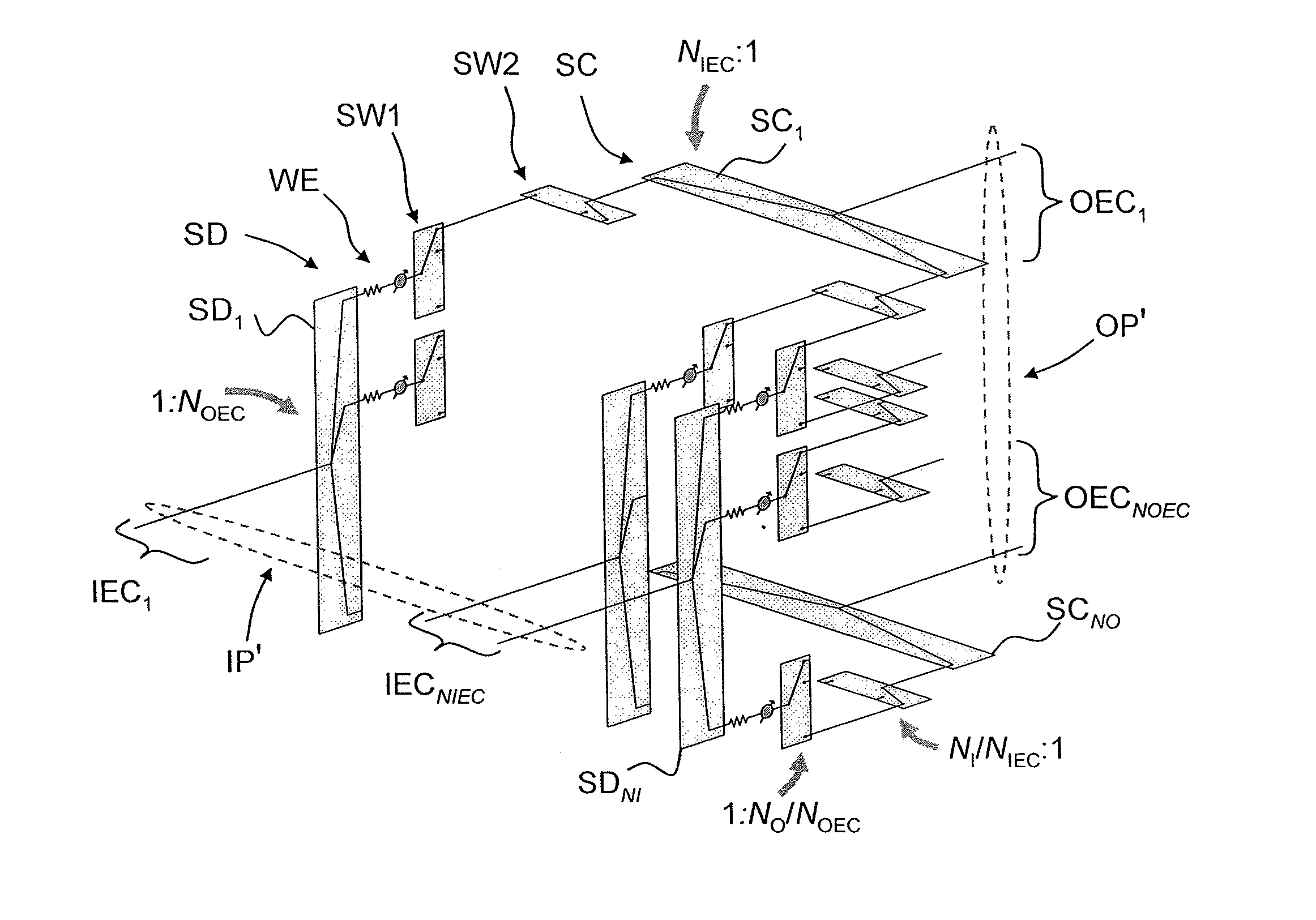
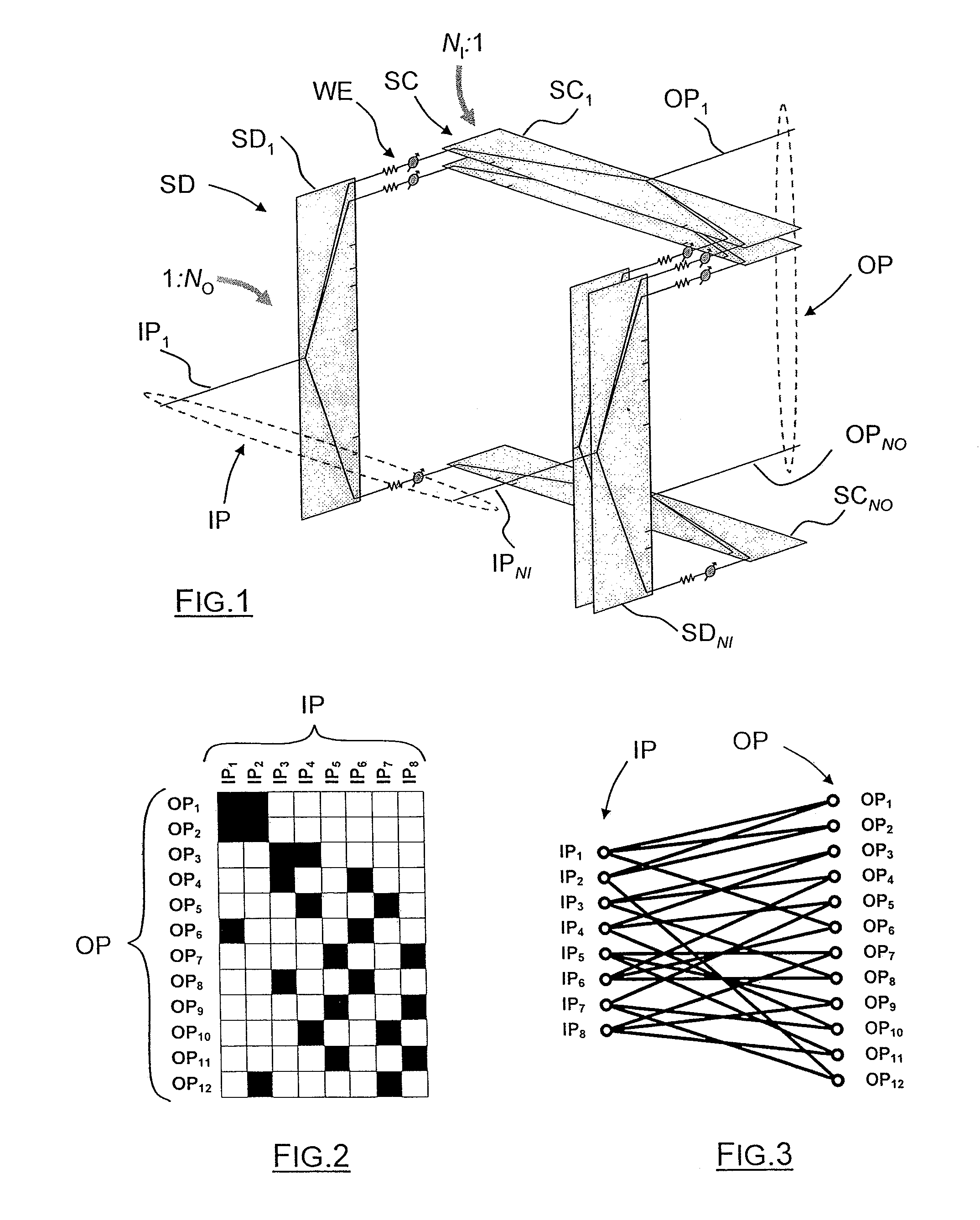
[0062]FIG. 1 represents a fully interconnected multi-beam BFN having NI input ports IP, labelled IP1-IPNI, and NO output ports OP, labelled OP1-OPNO. If this BFN is configured to operate in transmit mode, up to NB≦NI distinct beam signals are present at the input ports, and NO output signals, corresponding to respective linear combinations of the input signals, are present at the output port; according to the laws of electromagnetism, the antenna elements (not represented) fed by the output port signals generate, in the far field, up to NB=NI separate beams, one for each input beam signal. Conversely, if the BFN is configured to operate in receive mode, up to NE≦NI input signals are received at the input ports from the respective antenna elements (not represented); up to NO different linear combinations of these inputs are generated and provided at the output port; according to the laws of electromagnetism, each linear combination of the input signals correspond to a synthesized rec...


PUM


Abstract

A beam-forming network having: a plurality (NI) of input signal ports (IP); a plurality (NO) of output signal ports (OP); a weighting and interconnecting network (WIN) comprising a plurality of signal dividers (SD), phase and amplitude weighting elements (WE), switches (SW1, SW2) and signal combiners (SC), for associating each input port to output ports through respective weighting units; wherein either input (IP) or output (OP) ports, or both, are partitioned into disjoint equivalence classes (IEC, OEC), at least a majority of said equivalence classes having more than one port; and in that the network is either configured in order to associate each input port to at most one output port for each output equivalence class, or to associate each output port to at most one input port for each input equivalence class, or both. Also provide is a multibeam antenna comprising having such a beam-forming network, and an electronic circuit for implementing such a beam-forming network.

Description

FIELD OF THE INVENTION[0001]The invention relates to a reconfigurable beam-forming network, to an electronic circuit implementing it and to a multibeam array antenna comprising such a beam-forming network.[0002]The invention applies in particular to the fields of satellite communications, remote sensing and global navigation systems.BACKGROUND OF THE INVENTION[0003]A Beam Forming Network (BFN) constitutes the heart of any array antenna system, i.e. of any antenna system relaying on a set of radiating elements to generate one or more beams. It plays an essential role in different antenna architectures ranging from direct radiating arrays (DRAs) to the vast set of Array-Fed Reflector (AFR) antennas, including Semi-Active Multi-Matrix, Imaging or others configurations.[0004]More specifically, a Beam Forming Network performs the functions of:[0005]in an emitting antenna array, focusing the energy radiated by an array along one or more predetermined directions in space by opportunely pha...

Claims


Application Information

Patent Timeline
Patent Type & Authority Patents(United States)
IPC IPC(8): H01Q3/40
CPCH01Q3/40H01Q25/00H04B7/18515H04B7/2041
Inventor ANGELETTI, PIERO
Owner EUROPEAN SPACE AGENCY
Why Eureka
Try Eureka