Fuel injection system for a combustion chamber of a turbomachine

a technology of fuel injection system and combustion chamber, which is applied in the direction of machines/engines, mechanical equipment, light and heating equipment, etc., can solve the problems of increasing heat exchange area, and achieve the effect of simple, effective and inexpensiv

Active Publication Date: 2013-06-04
SN DETUDE & DE CONSTR DE MOTEURS DAVIATION S N E C M A
View PDF10 Cites 3 Cited by
  • Summary
  • Abstract
  • Description
  • Claims
  • Application Information

AI Technical Summary

Benefits of technology

[0010]A particular object of the invention is to provide a solution to this problem that is simple, effective, and inexpensive.
[0011]To this end, the invention provides a fuel injection system for an annular combustion chamber of a turbomachine, the system comprising support means for supporting and centering a fuel injector head, and a bowl arranged downstream from the support means and including at its downstream end an annular collar that extends radially outwards and that is cooled by air impacting against its upstream radial surface, wherein the collar includes means that are formed to project from or to be recessed into its upstream radial surface and that are designed to disturb the flow of cooling air and to increase the heat exchange area between said air and the collar.
[0012]These means give rise to disturbances in the stream of cooling air flowing over the upstream radial surface of the collar radially from the inside towards the outside, and they increase the heat exchange area between said cooling air and the collar. These means enhance the cooling of the collar by the flow of cooling air, with the collar being cooled both by impact and by the flow of cooling air over the collar.
[0015]Advantageously, each peg or stud is generally cylindrical in shape, being of a section that includes a first portion that is concave, plane, or with a reentrant angle, and a second portion that is convex or with a salient angle, the second portion being diametrically opposite from the first, which first portion is oriented radially towards the inside relative to the axis of the collar. This enables the quantity of heat flux that is exchanged between the cooling air and the pegs or studs of the collar to be increased by about 5% to about 10%. The stream of air flowing over the collar impacts against the pegs or studs, thereby creating air recirculation and increasing heat exchange between the air stream and the collar. The inner peripheral faces of the pegs or studs occupy an angle lying in the range about 40° to about 140°, for example lying in the range about 90° to about 120°, about the axes of the pegs or studs.
[0018]Advantageously, the pegs of one row are in a staggered configuration relative to the pegs of another row, thereby increasing the disturbances in the stream of cooling air.
[0021]The height or axial dimension of the pegs of an outer row may be greater than or equal to the height of the pegs of the or each inner row. When the height of the pegs in an outer row is greater than the height of the pegs in an inner row, the heat exchange areas of the pegs of the outer row are larger, thereby improving cooling of the radially outer annular portion of the collar, on which said outer row is located.

Problems solved by technology

These means give rise to disturbances in the stream of cooling air flowing over the upstream radial surface of the collar radially from the inside towards the outside, and they increase the heat exchange area between said cooling air and the collar.

Method used


Image

  • Fuel injection system for a combustion chamber of a turbomachine
  • Fuel injection system for a combustion chamber of a turbomachine
  • Fuel injection system for a combustion chamber of a turbomachine

Examples


Embodiment Construction

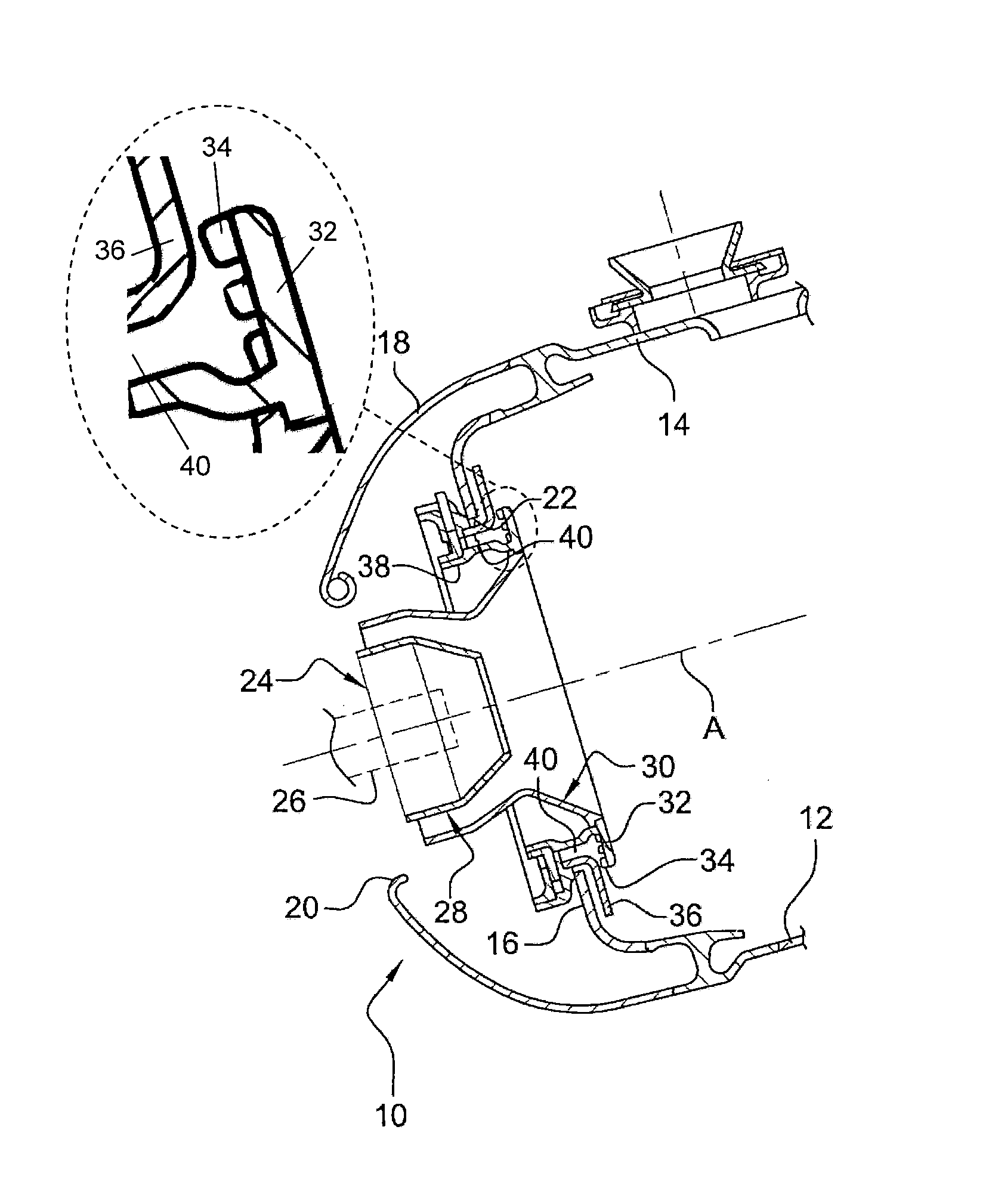
[0032]FIG. 1 shows an annular combustion chamber 10 of a turbomachine, such as an airplane turboprop or turbojet, the chamber 10 being arranged at the outlet from a diffuser (not shown), itself situated at the outlet from a compressor (not shown).

[0033]The chamber 10 comprises an inner wall 12 forming a body of revolution and an outer wall 14 forming a body of revolution, which walls are connected together at their upstream ends by an annular wall 16 forming a chamber end wall.

[0034]An annular fairing 18 is fastened to the upstream ends of the walls 12 and 14 of the combustion chamber and includes air-passing openings 20 in alignment with orifices 22 in the chamber end wall 16, which orifices have fuel injection systems 24 mounted therein, the fuel being delivered by injectors that are regularly distributed around the axis of the chamber.

[0035]Each injector comprises a fuel injection head 26 engaged in an injection system 24 and in alignment on the axis A of an orifice 22 in the cha...


PUM


Abstract

A fuel injection system for an annular combustion chamber of a turbomachine including a support device for supporting and centering a fuel injector head; and a bowl arranged downstream from the support device and including at its downstream end an annular collar that extends radially outwards and that is cooled by air impacting against its upstream radial surface is disclosed. The upstream radial surface includes a device which disturbs the flow of cooling air and increases the heat exchange area between the air and the collar.

Description

FIELD OF THE INVENTION[0001]The present invention relates to a fuel injection system for an annular combustion chamber of a turbomachine such as an airplane turboprop or turbojet.[0002]An annular combustion chamber comprises two walls forming bodies of revolution, respectively an inner wall and an outer wall, which walls are connected together at their upstream ends by an annular chamber end wall that has orifices, each having a respective fuel injection system mounted therein.[0003]A conventional fuel injection system comprises support means for supporting and centering the head of a fuel injector and a bowl of substantially frustoconical shape, which bowl is placed downstream from the means for supporting and centering the injector head, on the same axis as said means, and including at its downstream end an annular collar that extends radially outwards.[0004]The fuel injection system has a plurality of annular rows of air-passing orifices, the air being for mixing with the fuel de...

Claims


Application Information

Patent Timeline
Patent Type & Authority Patents(United States)
IPC IPC(8): F02G1/00
CPCF23R3/283F23R2900/03045Y02T50/675Y02T50/60
Inventor CAMERIANO, LAURENT BERNARDPIEUSSERGUES, CHRISTOPHESANDELIS, DENIS JEAN MAURICE
Owner SN DETUDE & DE CONSTR DE MOTEURS DAVIATION S N E C M A
Why Eureka
Try Eureka