Acceleration sensor and/or tilt sensor

a technology of sensor, which is applied in the direction of acceleration measurement using interia forces, instruments, surveying and navigation, etc., can solve the problems of only slight change, acceleration and/or tilt sensor permits only a limited sensitivity, and the hollow interior of the housing is distributed, etc., to achieve the effect of adequate surface tension, improved sensitivity, and suitable adhesion

Inactive Publication Date: 2013-06-04
TDK MICRONAS GMBH
View PDF6 Cites 3 Cited by
  • Summary
  • Abstract
  • Description
  • Claims
  • Application Information

AI Technical Summary

Benefits of technology

[0008]An advantage of the invention is that the fluid is only partially displaced from the neutral position or receptacle. In this context, displacement is understood to be exclusively a deformation of the surface of the fluid such that the portion of the fluid that is deflected does not run out, which is to say that a shared surface is formed with the portion of the fluid remaining in the receptacle. Investigations by the applicant have shown that with adequate surface tension and suitable adhesion of the fluid in the receptacle, the fluid takes the form of a meniscus, and formations delimiting the meniscus, in particular formations designed as housing parts, are obsolete.
[0009]In a refinement, the receptacle is designed as an open housing in such a manner that the receptacle has at least one lateral opening into which a subset of the fluid in the neutral position can be displaced by the external force. By this means, the sensor is made more robust, in particular with respect to impulsive accelerations. Preferably the housing parts can be made of a plastic. Notably, plastics that can be processed using lithographic processes in semiconductor manufacture, such as, in particular, SU8 photoresist, polyimide, and PMMA, may be used for this purpose. Preferably, the acceleration and / or tilt sensor can be designed as an integrated acceleration and / or tilt sensor. To this end, the receptacle is made on a wafer surface. A magnetic field sensor, preferably a Hall sensor, is integrated in the wafer surface, at least at one point on the receptacle where the housing has an opening. Multiple magnetic field sensors with different orientations may also be formed in this design in order to detect the different directions of application of a force. Preferably, the magnetic field sensors are formed in close proximity to the neutral position of the fluid.
[0010]It is preferable for the acceleration and / or tilt sensor, especially the parts of the acceleration and / or tilt sensor that do not include the magnetic field sensors, to be manufactured in a back-end CMOS process. Microfluidic structures of this nature can be applied by means of high-aspect ratio photoresist layers, such as SU8, polyimide, or PMMA, or by means of laminating techniques or bonding techniques. Subsequently, the channel structures are preferably lidded and filled with the ferrofluid. Alternatively, the microfluidic structures can also be applied to the underside of the substrate or can be etched into the substrate by means of bulk silicon micromechanics. The mobility of the ferrofluid on the substrate surface, in particular on the wafer surface, can be adjusted by specific surface modification in such a manner that the wetting, which is to say the contact angle of the meniscus between the substrate surface and the ferrofluid, either increases or decreases.
[0011]In particular, it is advantageous to match the dimension of the opening and the surface tension of the fluid to one another. This makes it possible to use fluids with different surface tensions. Moreover, different acceleration and / or tilt angle ranges can be measured by the sensor. It is a matter of course that the openings for a given surface tension should be made smaller for large acceleration ranges to be measured than they should for small acceleration ranges to be detected.
[0012]In another refinement, the acceleration and / or tilt sensor is designed with a ferromagnetic fluid, located in a receptacle, that can be displaced relative to the receptacle from a neutral position to an operating position by an external force, wherein the fluid is permanently magnetized, and wherein a magnetic field detector arrangement is located at the receptacle to detect a displacement of the fluid, wherein the receptacle has at least one lateral opening into which a subset of the fluid in the neutral position can be displaced by the external force, and that the dimensions of the opening and the surface tension of the fluid are matched to one another in such a manner that the fluid returns to the neutral position after removal of the external force.
[0013]A fluid of this nature is also known by the name “ferrofluid.” When the fluid is accelerated, at least regions of it are displaced, causing it to change its shape. This shape change causes a change in the magnetic field in the fluid's environment, which is measured with the aid of the magnetic field detector arrangement located in the magnetic field in order to detect the displacement of the fluid, and hence the acceleration. Since the fluid can exit the receptacle at the opening upon the occurrence of an acceleration and / or tilt, a relatively great change in the fill level of the fluid takes place in the receptacle. Consequently, the acceleration sensor according to the invention permits a simple and economical design. The acceleration and / or tilt sensor according to the invention can also be used as a vibration sensor.

Problems solved by technology

The acceleration and / or tilt sensor has the disadvantage that the fluid distribution in the hollow interior of the housing, and thus the magnetic field at the Hall sensors, changes only slightly when small external forces arise.
Consequently, the acceleration and / or tilt sensor permits only a limited sensitivity.

Method used


Image

  • Acceleration sensor and/or tilt sensor
  • Acceleration sensor and/or tilt sensor
  • Acceleration sensor and/or tilt sensor

Examples


Embodiment Construction

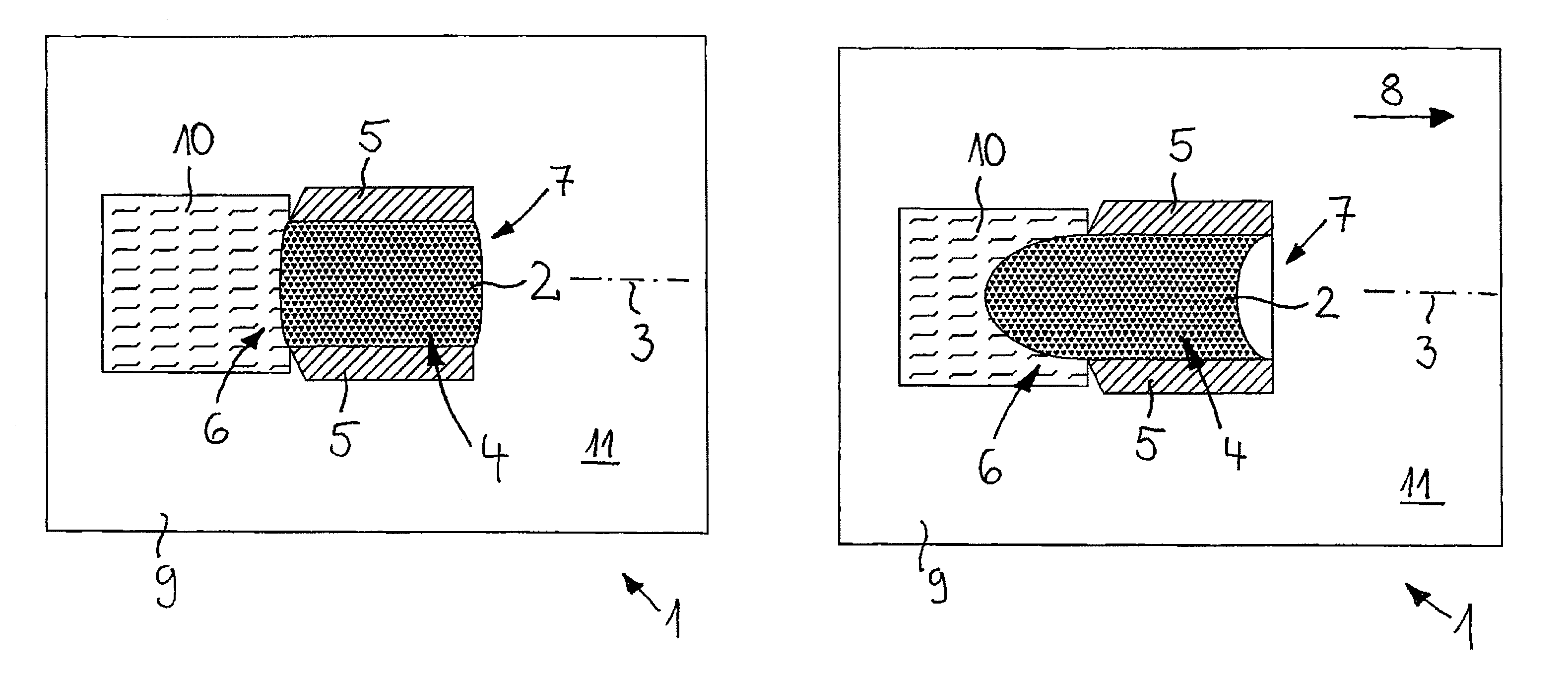
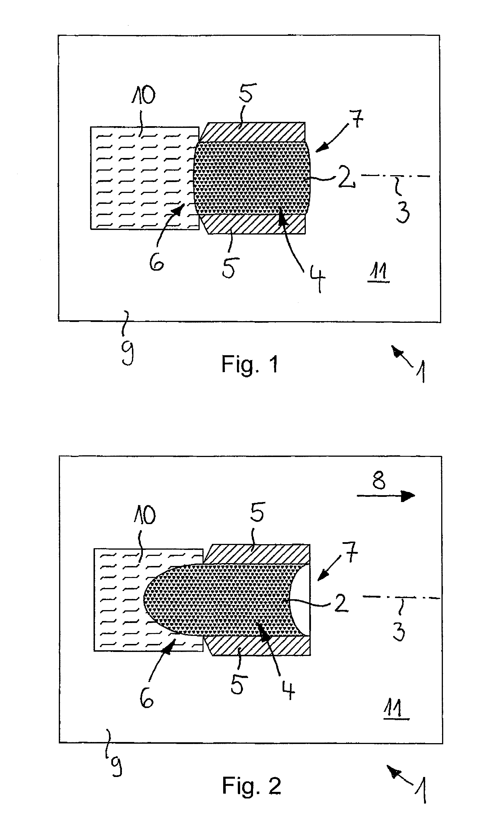
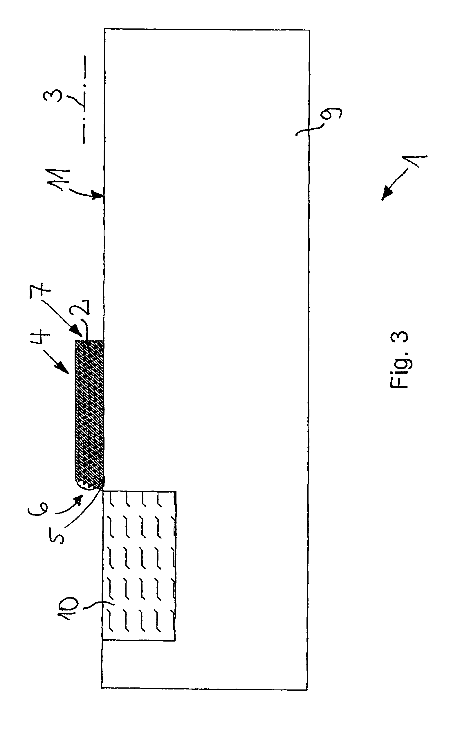
[0037]An acceleration sensor labeled overall as 1 has a ferromagnetic fluid 2, which is magnetized along a magnetization axis 3. The magnetization can be accomplished through permanently magnetized particles made of iron, nickel, or cobalt contained in the fluid that have been aligned along a magnetization axis 3 with the aid of a strong magnetic field.

[0038]The fluid 2 is arranged in a receptacle in such a way that it can be displaced relative to the receptacle by an acceleration acting on the acceleration sensor 1. In order to detect a displacement of the fluid 2, a magnetic field detector arrangement is integrated in the receptacle.

[0039]In the exemplary embodiment shown in FIGS. 1 through 3, the receptacle has a channel 4 whose longitudinal axis is located in the magnetization axis or runs parallel thereto. The channel 4 is surrounded by a wall 5, which is approximately cylindrical on its inner surface facing the acceleration 2. The inner surface of the wall 5 facing the channel...


PUM


Abstract

Acceleration and/or tilt sensor having a ferromagnetic fluid that is located in a receptacle, and the receptacle constitutes a neutral position for the fluid, and the fluid is permanently magnetized, and a magnetic field detector arrangement is located at the receptacle to detect a displacement of the fluid, wherein a portion of the fluid can be displaced relative to the receptacle from the neutral position to an operating position by an external force while maintaining a continuous surface with the portion of the fluid remaining in the neutral position, and the fluid returns to the neutral position after removal of the external force.

Description

BACKGROUND OF THE INVENTION[0001]1. Field of the Invention[0002]The invention concerns an acceleration sensor and / or tilt sensor having a ferromagnetic fluid that is located in a receptacle and that can be displaced relative to the receptacle from a neutral position to an operating position by an external force, wherein the fluid is permanently magnetized and / or the acceleration sensor has a magnetic field generator to generate a magnetic field that permeates the fluid, and wherein a magnetic field detector arrangement is located at the receptacle to detect a displacement of the fluid.[0003]2. Description of the Background Art[0004]An acceleration and / or tilt sensor of this nature is known from DE 10 2006 007 900 B4. The acceleration and / or tilt sensor has a closed housing as receptacle, which surrounds a hollow interior that is approximately half filled with the ferromagnetic fluid. Located below the bottom of the housing is a permanent magnet whose magnetic field permeates the flu...

Claims


Application Information

Patent Timeline
Patent Type & Authority Patents(United States)
IPC IPC(8): G01P15/11G01C9/18
CPCG01P15/105
Inventor ERDLER, GILBERTFRANKE, JOERG
Owner TDK MICRONAS GMBH
Why Eureka
Try Eureka