Illuminated finger sensor assembly for providing visual light indications including IC finger sensor grid array package

a finger sensor and array package technology, applied in digital data authentication, instruments, semiconductor devices, etc., can solve the problems of increasing the overall device footprint, limiting the space within each portable electronic device for additional hardware features, etc., and achieves compact size and convenient installation in an electronic device.

Inactive Publication Date: 2013-06-04
APPLE INC
View PDF28 Cites 15 Cited by
  • Summary
  • Abstract
  • Description
  • Claims
  • Application Information

AI Technical Summary

Benefits of technology

[0009]In view of the foregoing, it is therefore an object of the present invention to provide a finger sensor assembly that is relatively compact in size, relatively easy to install in an electronic device, and provides visual light indications.

Problems solved by technology

As portable electronic devices become increasingly smaller in size, space within each portable electronic device is becoming limited for including additional hardware features.
Moreover, including a fingerprint sensor in a portable electronic device may increase the overall device footprint.

Method used


Image

  • Illuminated finger sensor assembly for providing visual light indications including IC finger sensor grid array package
  • Illuminated finger sensor assembly for providing visual light indications including IC finger sensor grid array package
  • Illuminated finger sensor assembly for providing visual light indications including IC finger sensor grid array package

Examples


Embodiment Construction

[0020]The present invention will now be described more fully hereinafter with reference to the accompanying drawings, in which preferred embodiments of the invention are shown. This invention may, however, be embodied in many different forms and should not be construed as limited to the embodiments set forth herein. Rather, these embodiments are provided so that this disclosure will be thorough and complete, and will fully convey the scope of the invention to those skilled in the art. Like numbers refer to like elements throughout, and prime notation is used to indicate similar elements in alternative embodiments.

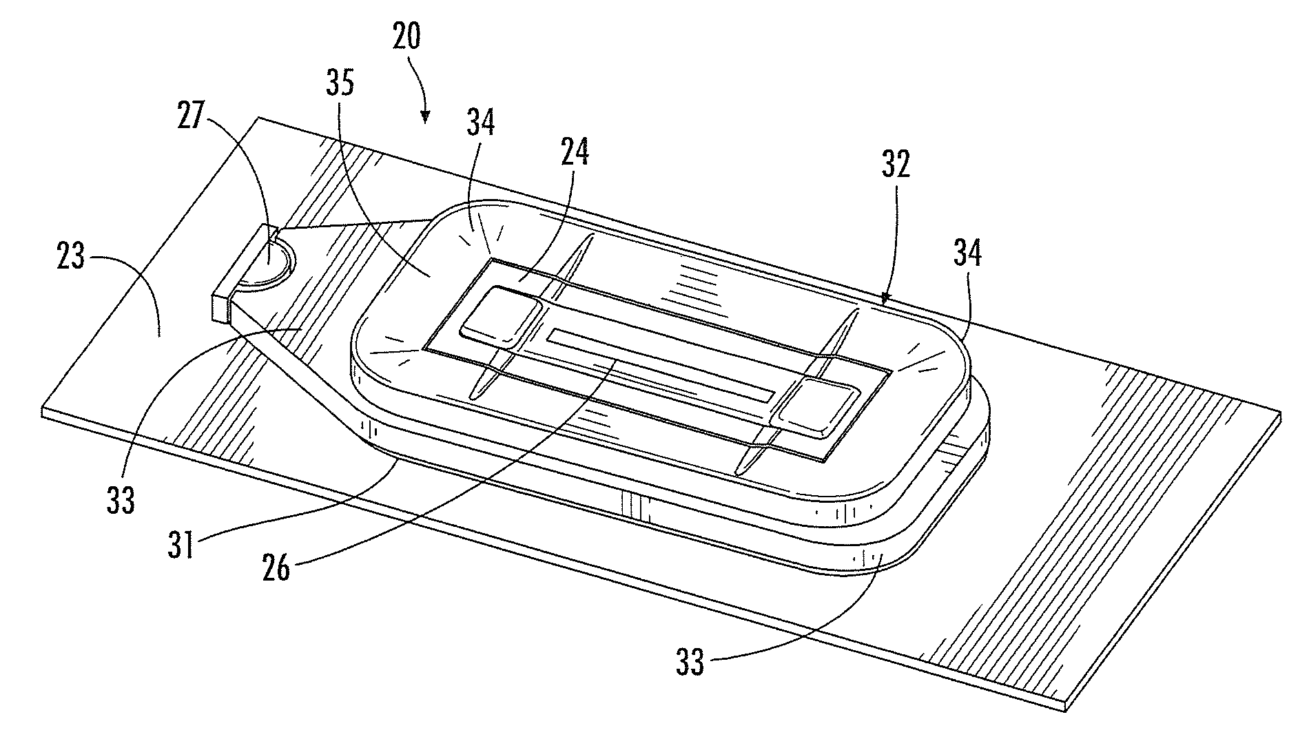
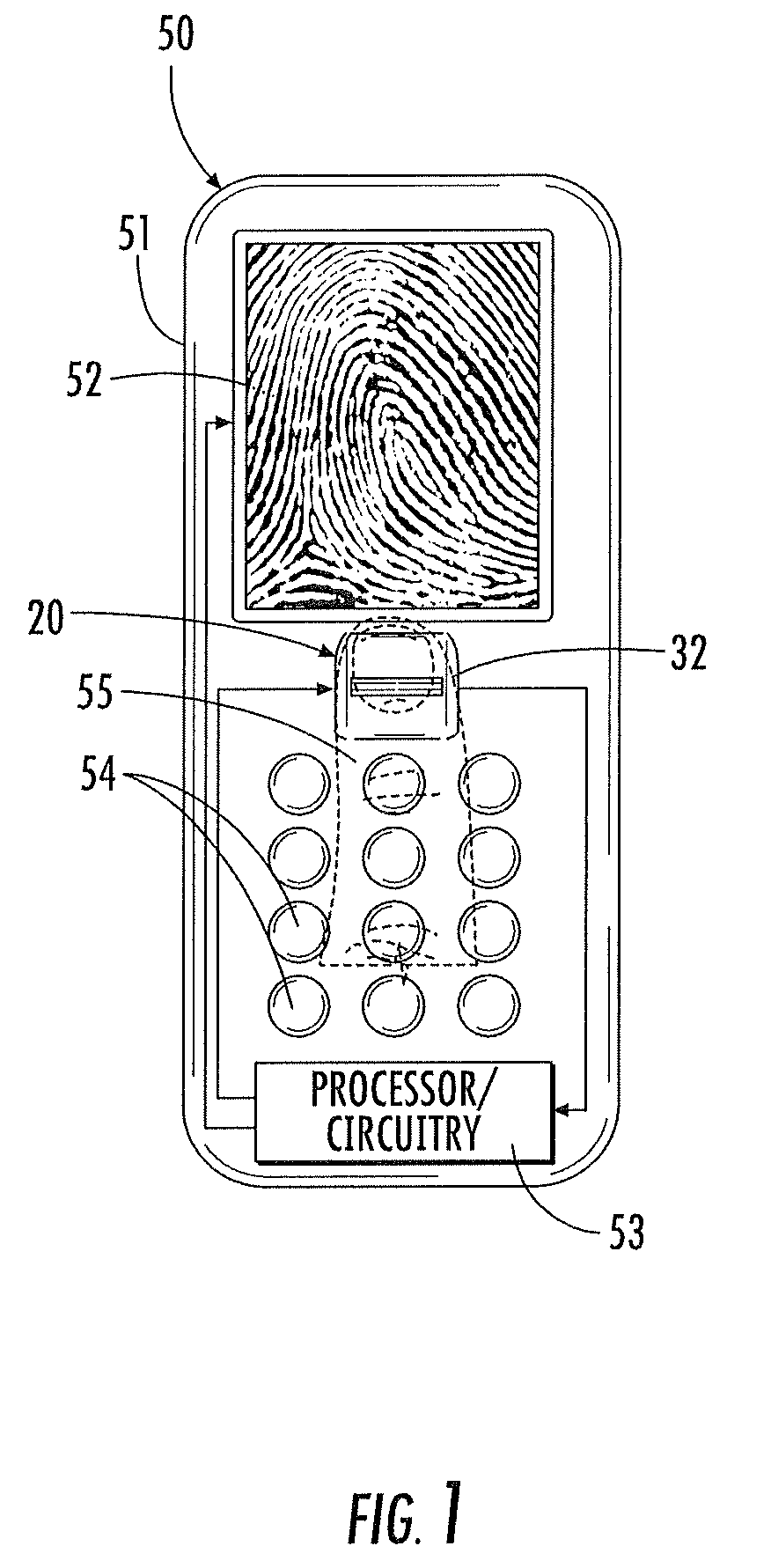
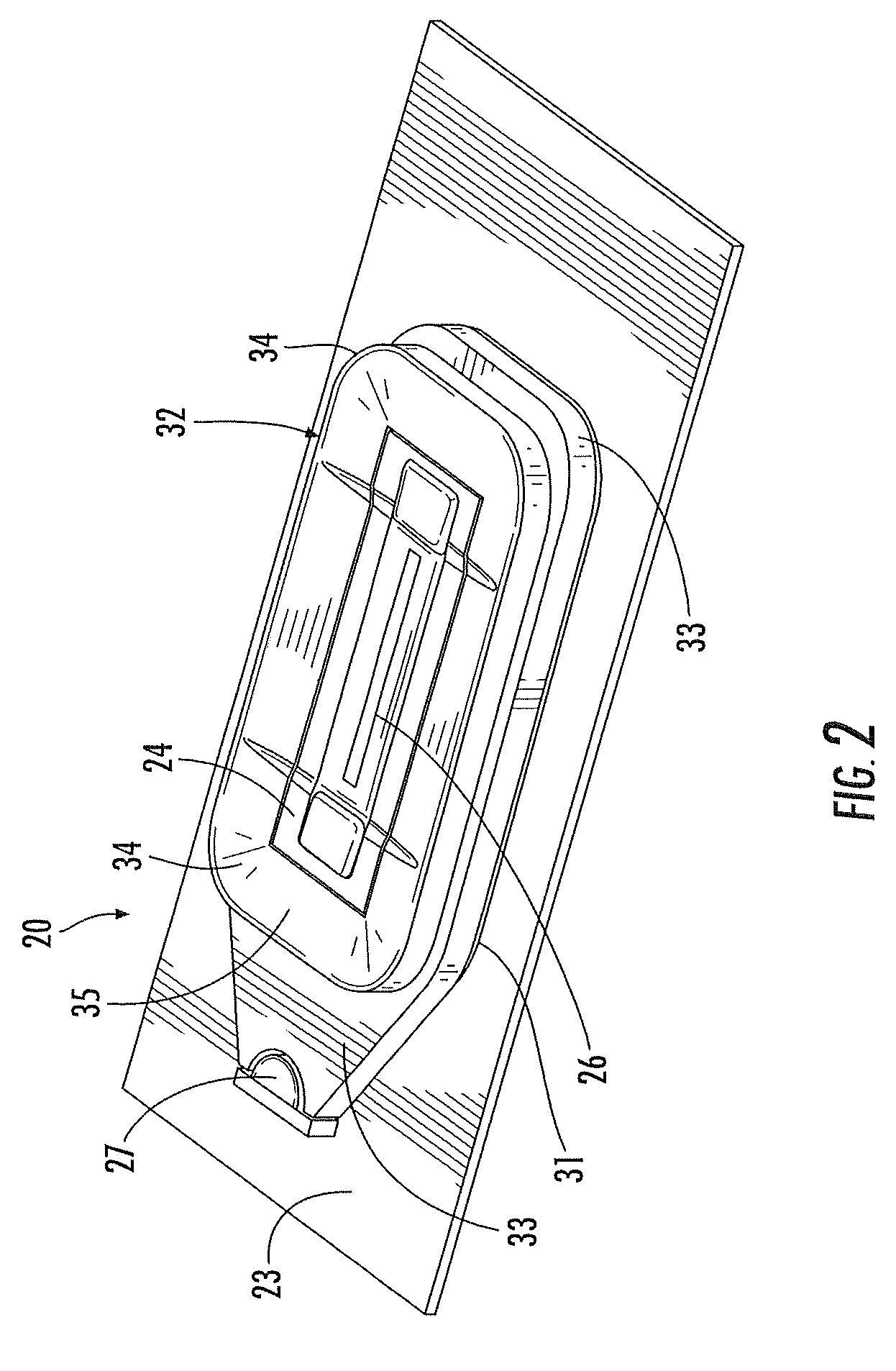
[0021]Referring initially to FIG. 1, an embodiment of a finger sensor assembly 20 in accordance with the present invention is now described. The finger sensor assembly 20 is illustratively mounted on an exposed surface of a cellular telephone 50. Of course, the finger sensor assembly 20 can also be used other portable and stationary electronic devices as well.

[0022]The cell...


PUM


Abstract

A finger sensor assembly may include a circuit board and an integrated circuit (IC) finger sensor grid array package including a grid array on a lower end thereof mounted to the circuit board, and a finger sensing area on an upper end thereof. The finger sensor assembly may further include at least one visible light source carried by the circuit board and a visible light guide optically coupled to the at least one visible light source. The at least one visible light source may at least partially laterally surround the upper end of the IC finger sensor grid array package to provide visual light indications. The IC finger sensor grid array package may also include circuitry for controlling the at least one visible light source.

Description

FIELD OF THE INVENTION[0001]The present invention relates to biometric sensing, and more particularly to finger sensor assemblies providing visual indications and related methods.BACKGROUND OF THE INVENTION[0002]Fingerprint sensing and matching is a reliable and widely used technique for personal identification or verification. In particular, a common approach to fingerprint identification involves scanning a sample fingerprint or an image thereof and storing the image and / or unique characteristics of the fingerprint image. The characteristics of a sample fingerprint may be compared to information for reference fingerprints already in a database to determine proper identification of a person, such as for verification purposes.[0003]A particularly advantageous approach to fingerprint sensing is disclosed in U.S. Pat. No. 5,953,441 to Setlak and assigned to the assignee of the present invention. The fingerprint sensor is an integrated circuit sensor that drives the user's finger with ...

Claims


Application Information

Patent Timeline
Patent Type & Authority Patents(United States)
IPC IPC(8): H01L27/14G06K9/00G06V40/13
CPCG06F21/32G06K9/00013G06K9/00919G06V40/13G06V40/63
Inventor SETLAK, DALE R.MCKINNEY, JOHN DAVID
Owner APPLE INC
Why Eureka
Try Eureka